
YT International BF109E - Wing construction.The wing for this ARF model is not to dissimilar to other ARF wings in terms of required finish. Simply glue hinges, fit servos, control horns, and wheels. Join together and there you have it. Lets get started. |
 |
 |
 |
 |
 |
 |
| 1. Click to enlarge | 2. Click to enlarge | 3. Click to enlarge | 4. Click to enlarge | 5. Click to enlarge | 6. Click to enlarge |
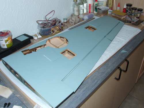
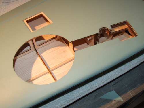
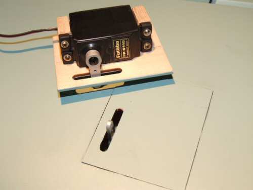
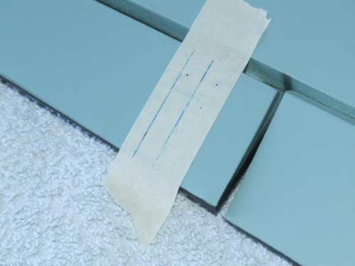
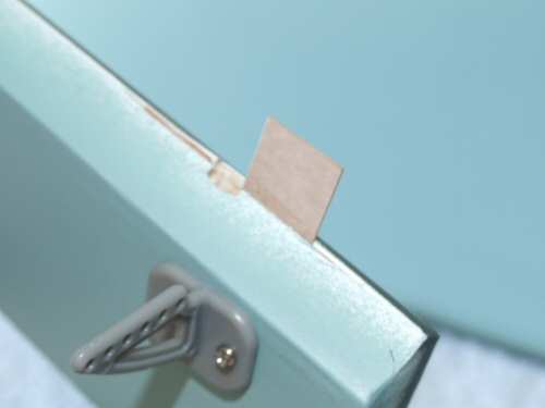
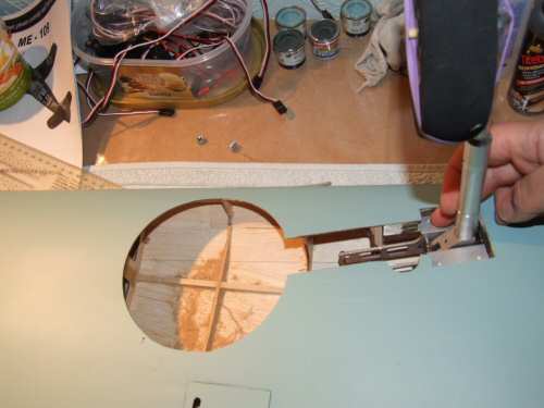
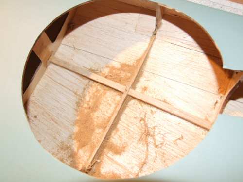
Pic 1. First job with the wing is to cut out the sections for the 2 servo blocks, and the wheel well. I find it useful when cutting these lines to trace the cut with a soft pencil beforehand. Pic 2. Exposed the structure of the wing and . . . Pic 3. the reasonable laminations to support the retracts. Pic 4. The servos are screwed to 2 basswood blocks that are epoxied to the door. I found it necessary to sand the excess paint from the doors to get them fitting correctly. Pic 5. Alignment is drawn for the control horns before installation. Pic 6. Normally I would use the synthetic fabric hinges for the control surfaces, but I have decided for this model I will use Robart pin hinges. I am working on the theory that this model should last more than a season! After making the hole for the pin I bridged the surrounding area (that was cut out for the fabric hinges) with 1/64" ply. This should add some strength to improve the security of the pin. Before installation I scuffed up the pins to ensure they gave good key. The pins will be installed with Polyurethane glue. Excess can be wiped away with cotton buds soaked in methanol as it foams. |
 |
 |
 |
 |
 |
 |
| 1. Click to enlarge | 2. Click to enlarge | 3. Click to enlarge | 4. Click to enlarge | 5. Click to enlarge | 6. Click to enlarge |
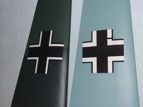
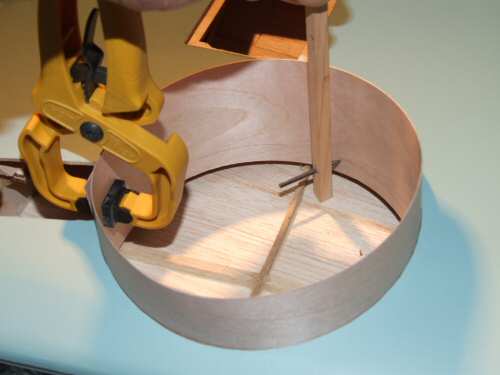
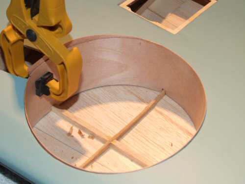
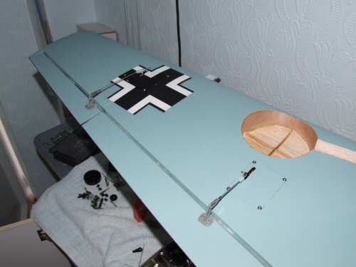
Pic 1. Before I install the control surfaces I added the insignia top and bottom wing. Rather than use the decals I once again created templates for this process. See the fuselage for details. Pic 2. To test the fit of the retracts I removed the cylinder and push rod from one assembly and positioned it in the wing. Using the wheels supplied there was not much room in the wing for it to comfortably receive the wheel. First obstacle was a rib that passes directly under where the wheel needs to fit so I took my Dremel and sanded it down to the same depth as the spar. Pic 3. Shows the result of the sanding process. While the wheel now fitted nicely I decided I wanted something a little closer to the actual wheel style. Fortunately a fellow flyer I met at RAF Coltishall, Graham of Tiger Models had something to fit the bill so I ordered a set. Pic 4. The plastic wheel wells that come with the kit are your typical ARF tray style. I decided to line the wells with 1/64" ply which is a common modification. Without a template I began the process of creating one! I started with a strip of 1/64" ply made into a circle that fitted tight into the well ensuring the overlap was in the OLEO trough. This not only helps to hide the joint it also provides a slot to clamp the overlap! With the tube seated as far down as possible I drew a simple trace line all the way round the bottom of the wing following the contour of the top sheet. Pic 5. Once I cut round the line I had a well lining that follows the profile of the wing. To make it fit all of the way down I cut notches for the rib and spar. I glued the well in position and allowed it to dry thoroughly overnight. Pic 6. Behind the well lining I installed some fillets to both sides of the OLEO trough, this will provide support for the ply while sanding the profile of the OLEO trough later on. |
 |
 |
 |
 |
 |
 |
| 1. Click to enlarge | 2. Click to enlarge | 3. Click to enlarge | 4. Click to enlarge | 5. Click to enlarge | 6. Click to enlarge |
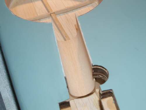
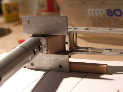
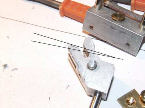
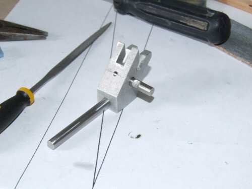
Pic 1. First I sanded the lip of the well down to the covering - very carefully I might add! Pic 2. I cut the well lining to the profile of the OLEO trough which was lined with a thin sheet of balsa. Had I thought about it a little more I might not have cut the cloth to expose the notch that takes the spring for the standard wire legs - Doh!!! Pic 3. The retracts hold the wheels at 90°, but to be more scale the retract angle should be 80°. There are a few ways to achieve this. First is to mount the retract blocks on wedges of hardwood. While giving the appearance of the correct angle when retracted the wheel fits tight into the wells touching the top sheet and I believe (from what I have read) they are unable to lock and remain up from the air pressure. No major problem but I wanted to go for something less obvious. I made a template of the required angle and shimmed the stop bar with 2mm of scrap ply. This gave a perfect fit to 80°. Pic 4. Close up of the shim, which now needs to be replaced with metal and fixed in position. Pic 5. Shown here are the lines of cut. The top line is the current 90° position and the lower line is the "to be cut" 80° position. Pic 6. The aluminium block was cut using a Dremel first and then a file. If you have a go at this method be very careful with the process as it can go horribly wrong if you go over zealous with the cutting - take small pieces off at a time and test fit regularly . After cutting was finished I cleaned everything up and began assembly. The shaft that makes the pivot for the retract is ground deeper than I would normally before installing with a grub screw. Note I used a shorter screw than was originally installed so that more thread remains for the shim to be bolted in position using the same thread. I did this because I did not want to drill and tap another hole in then block potentially weakening the setup ! |
 |
 |
 |
 |
 |
 |
| 1. Click to enlarge | 2. Click to enlarge | 3. Click to enlarge | 4. Click to enlarge | 5. Click to enlarge | 6. Click to enlarge |
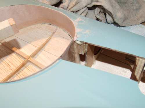
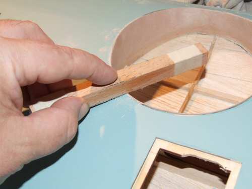
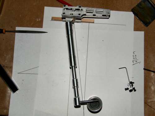
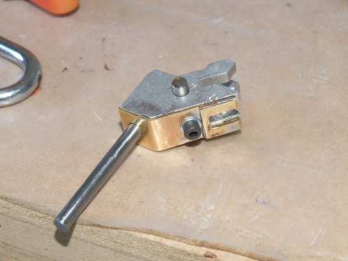
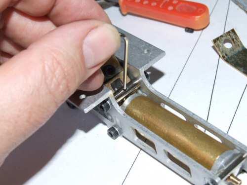
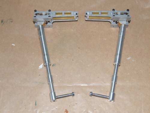
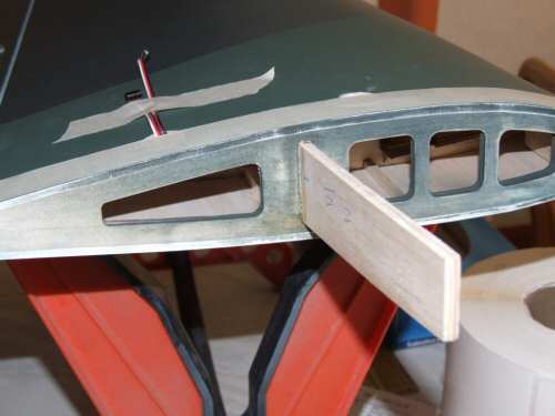
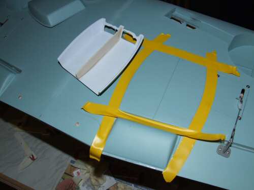
Pic 1. The shim is 1mm solid Brass that has a 5mm hole at one end to slide over the OLEO pin, and folded over at the other end to make the required 2mm. Pic 2. With everything back in position small adjustments can be made loosening the bar shown and turning it. I did not notice initially the bar was offset (ace metric) on the threads until much later. There is at least 1mm worth of adjustment here to play with. I adjusted the mountings so that there was just a little movement that could be detected. After adjustment I made sure the piston traveled freely. Pic 3. Ta Daa, the newly acquired 80° retracts with no modification to the wing. The modifications take about 4 hours to complete. Pic. 4. Continuing on with the wing I finished off the installation of the control surfaces and servo installation using Futaba type "E" horns. Pic 5. The brace was test fitted and then installed into one side first. With such a large brace I now used Polyurethane glue as it really holds the wood solid! Masking tape was applied to both mating surfaces along the edge to prevent excess glue from ruining the paintwork. Pic 6. the 2 halves glued with Polyurethane on the brace and 12 minute epoxy on the root ribs. |
 |
 |
 |
 |
||
| 1. Click to enlarge | 2. Click to enlarge | 3. Click to enlarge | 4. Click to enlarge | 5. Click to enlarge | 6. Click to enlarge |
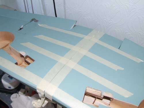
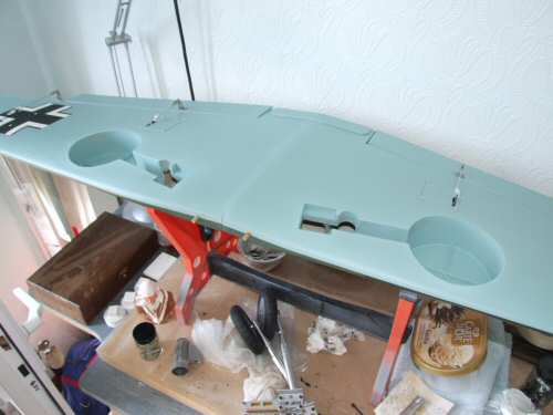
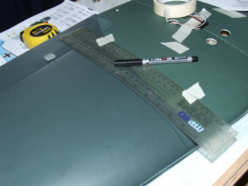
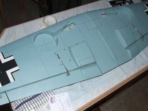
Pic 1. To Finish off the wheel wells were given a quick coat of RLM 65 Hellblau (closest match Humbrol 65). Pic.2 The radiator parts were installed as per instructions, but the main radiators I installed a strip of balsa down the midle to provide some additional support to the plastic shell. I prepared the surfaces by cleaning with a quick rub of acetone followed by course sandpaper on both surfaces. Tape was used on the installation line to make a clean break for the excess glue that escapes from the side! Pic 3. Starting to draw a few lines on the wing, not many . . . just the main panel lines. I used a 0.7mm permanent marker pen for this task. Pic 4. The underside was given the same treatment. |