
Brian Taylor 1/5.33 Spitfire build
|
 |
 |
 |
 |
 |
 |
| 1. Click to enlarge | 2. Click to enlarge | 3. Click to enlarge | 4. Click to enlarge | 5. Click to enlarge | 6. Click to enlarge |
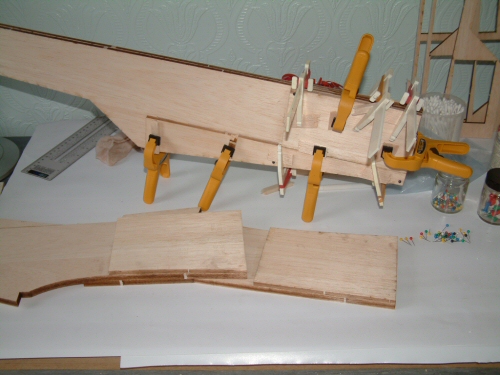
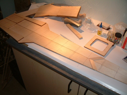
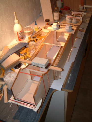
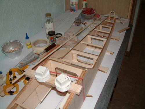
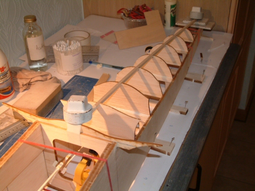
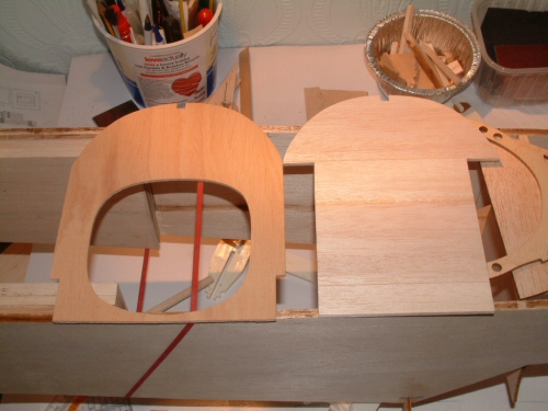
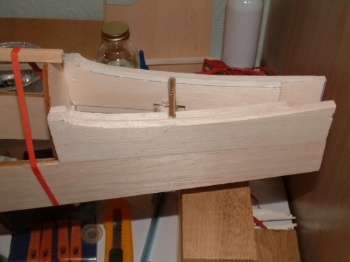
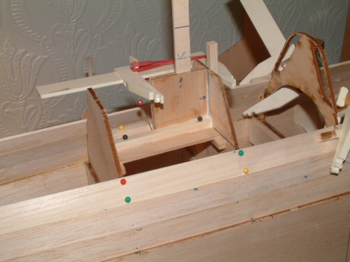
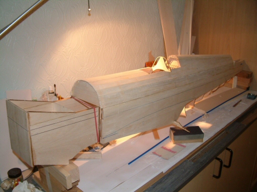
First in line for the building board is the fuselage. I am building the fuse on a very flat pin board which has been covered with paper to protect the surface. Pic 1. All of the vertical walls and formers for the fuselage are made from 1/4" balsa sheet except the front sheets which are 3/8". These parts require laminating with each other to make the 2 halves of the side walls. This is my first time building with laser cut parts and I am very pleased with the fits so far. Pic 2. With both halves now complete I aligned them together and traced the positions of the formers and cross members from the plans. Pic 3. To ensure alignment I use a cotton thread under tension between 2 pins as my centre datum line. The centre points were marked on all formers and a right angle drawn on the building board to assist alignment. In the picture all of the main formers are in position (5,7,9,11) and the front 1/8" ply bulkhead and 1/4" balsa fuel tank housing (top) have been added. These parts are not provided in the laser cut kit and have to be cut from stock. The former at bulkhead position 4 has not been installed as this needs some consideration with respect to scale issues. Scrap wood is currently making the positions. Pic 4. All the minor formers and re-enforcing for the main formers have been added. Former 13, which holds the retractable tail wheel, seen at the tail end has not been fixed into position yet. Pic 5. While I had the fuse flat on the board I added the lower formers into position and the 1/4" stringer. Pic 6. The fuselage has been turned over and supported so that the surface is perfectly flat. I have decided to fit former 4 now made from 1/8" balsa laminated to 3mm light ply. The instrument panel for the cockpit will eventually be mounted here. This is a deviation from the plans with the intention of having a more scale like cockpit. |
 |
 |
 |
 |
 |
 |
| 1. Click to enlarge | 2. Click to enlarge | 3. Click to enlarge | 4. Click to enlarge | 5. Click to enlarge | 6. Click to enlarge |
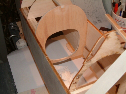
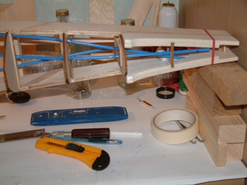
For some reason the Bob Holman laser cut kit includes formers F3, and F4, but not F2. Each of these formers are exactly the same so I used the laser cut parts in position F2 & 3. The modified former at F4 was cut using F3 as a template and incorporated in the modified F4 shown in the previous section. Pic 1. Now shows the 1/4" firewall installed with the thrust line carefully marked. All of the main formers are shown in position with the exception of F7 which sits right in the middle of the port camera service hatch. I am thinking of adding a camera if I can work things out so I will consider options before committing materials. Pic 2. The modified F4 in position also supporting the 1/4" stringer now fixed in position. Pic 3. Shows F13 which mounts the retractable tail wheel has been strengthened with some triangular section and drilled accordingly for the tail wheel frame. I have fixed in position with epoxy putty the nuts that will retain the bolts at installation. Pic 4. The tailplane supports were fabricated from 1/4" balsa with an insert piece of 1/4". The plans call for 3/8" inner section but I am out of stock so will laminate another 1/8" at a later date if required. It is apparent that there will be much sanding in this area when shaping the final curves! Pic 5. The snakes for the elevator, rudder and retractable tail wheel were installed drilling holes in the appropriate positions on the formers for a good route. Just visible in the centre of the picture at F12 I have added a brace of light ply to secure all 3 snakes tightly. Every hole is glued with rubber glue to secure the snakes in position (Zappa Dappa Goo 2). Pic 6. Wanting to make as much a scale appearance to the cockpit I have run the snakes along the sides of the fuselage Just above the 1/4" balsa brace. 2 snakes on the starboard side for rudder and elevator (visible in this picture) and one to port for the tail wheel. To get the snaked into the front section I had to cut slots in the side wall to permit access. These were then back filled with shaped balsa and sealed in position with thixotropic polyurethane. I recommend anyone who plans on adopting this method for themselves to build into the side walls the slots before laminating the sheets. This would be much cleaner removing the need for cutting the outer sheet. Note to self - better forward planning required! On the subject of forward planning ideas of having a camera in the model have all but faded away as I believe the weight penalty will be too high. |
 |
 |
 |
 |
 |
 |
|---|---|---|---|---|---|
| 1. Click to enlarge | 2. Click to enlarge | 3. Click to enlarge | 4. Click to enlarge | 5. Click to enlarge | 6. Click to enlarge |
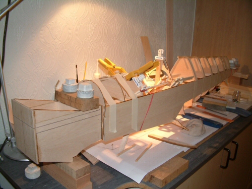
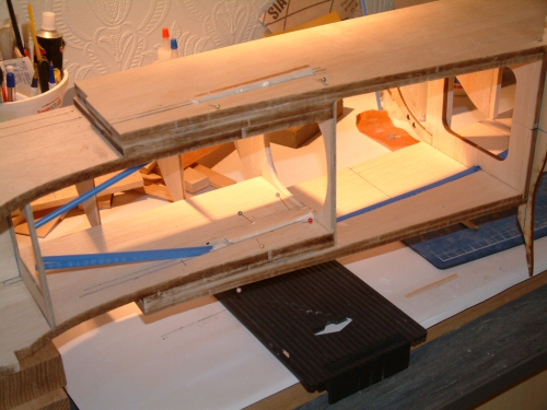
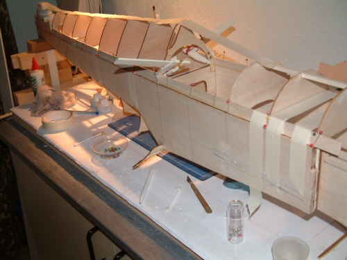
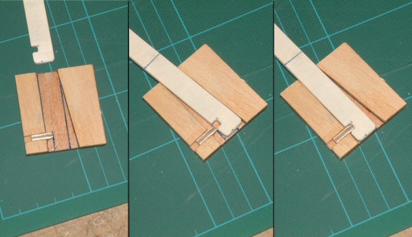
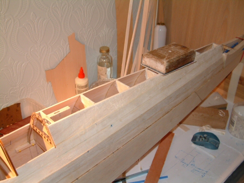
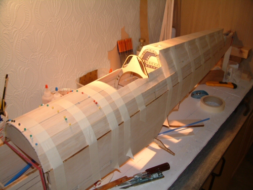
Time to walk the plank! On my Mick Reeves Spitfire build I used thixotropic polyurethane on the planks, which worked fine until the sanding process, when the excess foam sanded less favourably to the balsa causing some careful work in some areas to get a good smooth finish. This time I am trying aliphatic glue which I last used for the rivets on the fuselage. I found it sands much easier than PVA so I am going to give it a go this time. Pic 1. shows the first strips or 3/32" balsa planks cut 18mm wide running down the side in one length. I will use harder grain at the bottom and medium density towards the top. Pic 2. Before all of the planking is on the upper fuselage I have installed a frame to receive the radio mast. The frame is the same as the one I designed for the Reeves Spitfire and is very simple. The radio mast core fits down a slot and tilts back to the vertical engaging on a small tong at the same time. The fit is snug but not tight. The 3 pictures show the idea of the two parts, sliding in the antenna, and finally locking into position. Pic 3. Shows the frame in position with balsa supports to provide some strength. Care was taken to ensure the mast was held vertically. Planking can also be seen progressing in this shot. Pic 4. Planking on the side walls completed the excess from the planks was flattened to accept the top 1/2" balsa top sheet. Prior to installing the top sheet I installed former 5 supported on some scrap 1/4" square balsa. The instructions tell you to hollow this part out but I have opted not to for fear of over hollowing! Pic 5. The planking on the top side is now complete and will receive a rough sanding when fully dry. Pic 6. Roughly carved and some shaping now complete I turned my attentions to the underside. The plans are not too strong on detail in this area, particularly on the faring and the wing root. What is clear however, is the need to build the wing sections before getting involved with the underside. I therefore decided to move to the wing construction. |
This rebuild has been halted while I get my business establised. It will continue, but I currently do not know when! |