
 |
 |
 |
 |
 |
 |
| 1. Click to enlarge | 2. Click to enlarge | 3. Click to enlarge | 4. Click to enlarge | 5. Click to enlarge | 6. Click to enlarge |
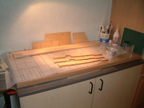
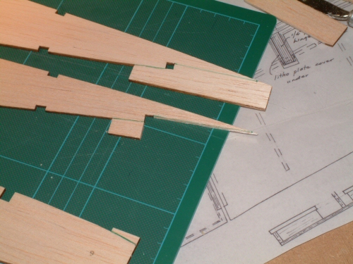
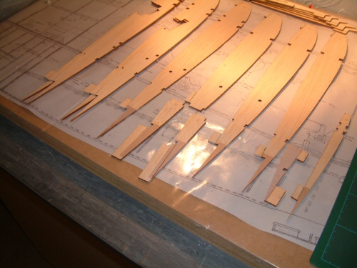
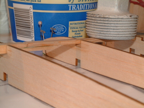
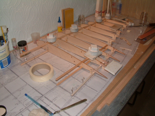
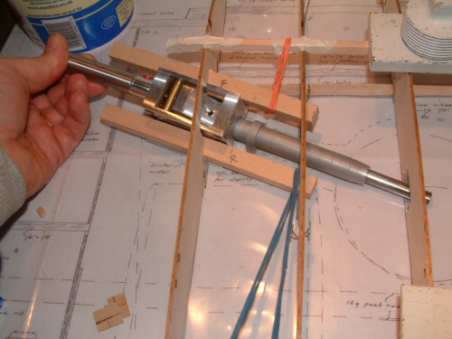
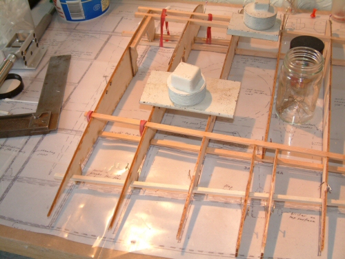
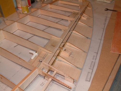
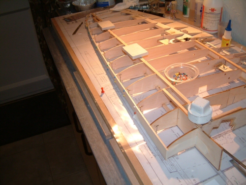
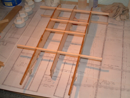
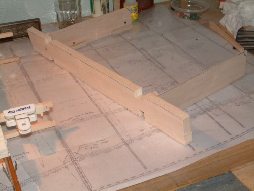
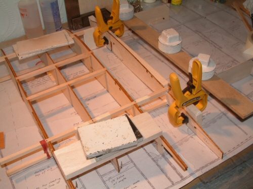
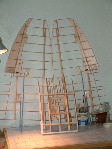
First things first. Clear the desk of everything!! In addition I always check the building board is perfectly flat before starting the wings. For the wings I am going to use spruce 1/4" x 1/4" and 1/8" x 1/4" for all spars in preference to balsa. Pic 1. In my humble building corner the stage is set. Ribs were removed from balsa sheets and sorted into port & starboard sides and centre parts. My firstproblem is the retract system. Lenny uses a much bigger block for the retract mechanism compared to the unitract unit detailed on the plans. Because the pivot points are not in the same location on the two units the 1/2" beach beams will need to be sunk further into the wing to accommodate the larger units and to carefully re-position the pivot point. Pic 2. The tabs on the ribs are very large and I have reduced them in size before assembly to make the cuts more accurate and simplify their removal later in the build. Picture shows rib 3 before and after this treatment. Pic 3. The plans call for 1/32" ply reinforcement on the tail end of the ribs that overhang the flaps. I have used 1/64" ply on both sides. Prep work completed I am now ready for basic assembly to begin. Pic 4. First off I glue the end and a few mid ribs to the top spar. Not the position of each rib is marked out with pins. This helps me just put the ribs in without having to worry about locating them. All I have to concentrate on is glue install & make level with a set square. Pic 5. Once dry I begin installing the remaining ribs and discover a discrepancy. Rib 10 is the first rib (according to the plans) that has the reduced 1/8" x 1/4" spar spliced into the 1/4" x 1/4" spar. What I did not notice until I was gluing the ribs was the notch in rib 10 was deep enough to accept 1/4" x 1/4". I corrected this quickly by sliding in a small slice of 1/8" x 1/4" to make up the difference. Not a major issue but one worthy of note. Pic 6. After the ribs dried I installed the remaining spars and sub ribs 3a and 4a. Note ribs 1D and 2 have not yet been installed pending the retract modification. |
 |
 |
 |
 |
 |
 |
| 1. Click to enlarge | 2. Click to enlarge | 3. Click to enlarge | 4. Click to enlarge | 5. Click to enlarge | 6. Click to enlarge |
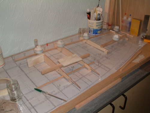
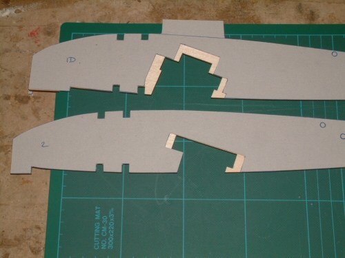
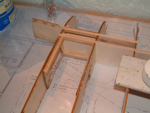
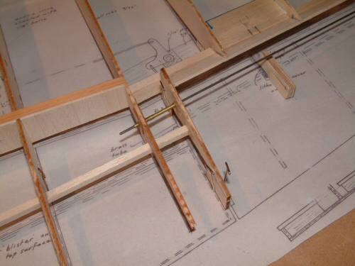
Pic 1. Now it is time to have a go at ribs 1D and 2. Both of these ribs support the 1/2" beach bearers for the retracts. As mentioned earlier the retracts specified on the plans are Unitract, which are much smaller than the units I have purchased from Lenny Sarbin. I started by using the balsa ribs and looking for the areas that would require trimming. After many cuts, measures and adjustments I finally got the blocks in position. I was particularly careful not to alter the angle of the beams and the position of the beams vertically. However, it was necessary to alter the width of the cut-outs to 66mm to accommodate everything comfortably. The profile cut into rib 1D was moved more forward to align the oleos with the datum line on the plans. The picture shows everything in position satisfactorily. Not visible in the picture and worthy of note the retracts do not fit fully onto the beams and are about 1.0mm short of resting on the beams. I am leaving them like this to have some room for adjustment later. Pic 2. Card templates show the increased areas to be cut on the 1/8" ply ribs that will be used. Note you can see the area cut from the front of 1D is greater as stated to get the all important lineup of the oleos. Both left and right ribs were cut at the same time to ensure they were absolutely identical. Pic 3. Once cut and laminated with the ply reinforcements the ribs were installed. Rib 1D was cut to accommodate the main brace before installation. I have also installed a strip of 1/4" spruce to strengthen the narrow "bridge" at the top of rib 1D. Pic 4. With the main brace installed the remainder of rib 1D was installed which was also reinforced with 1/4" x 1/4" support on the outside of this joint to give more rigidity. Pic 5. Other installations included 1/16" webbing to the main spars. 1/4" x 1/2" balsa to the trailing edge of the aileron housing which required trimming to follow the profile of the ribs on the underside. once dry I also added the 1/16" sheet to the tapered surface of the ribs (clearly visible in the picture). Pic 6. I also decided to add 1/16" webbing to the rear spars having seen several comments in forums that "this was a wise thing to do" - so I took the advice. |
 |
 |
 |
 |
 |
 |
| 1. Click to enlarge | 2. Click to enlarge | 3. Click to enlarge | 4. Click to enlarge | 5. Click to enlarge | 6. Click to enlarge |
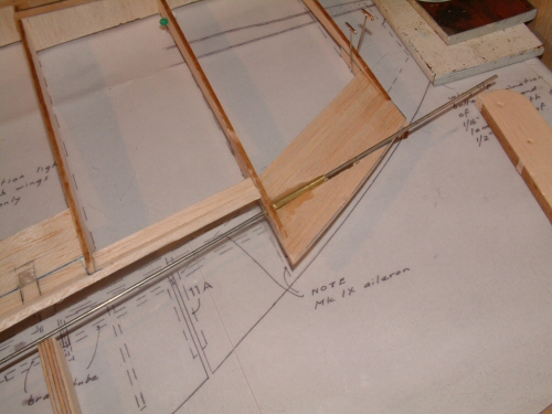
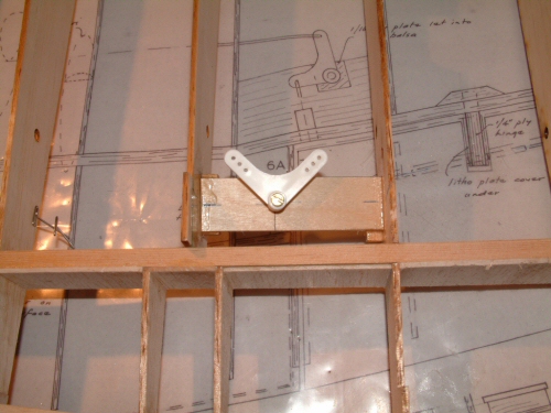
Time to fit the wire hinge and bearing for the aileron. I have to admit I am not looking forward to the aileron construction as it gave me so much grief on the Mick Reeves build. Mainly my inexperience with the situation I suppose but nonetheless a daunting task! Pic 1. The 12 gauge wire runs in a brass tube baring. The process starts by installing brass tube on the inside of the aileron, and . . . Pic 2) the outer edge. Care needs to be taken drilling this hole as there is not very much room to play with. I ran the wire down the tube to make sure everything lined up OK before using epoxy to fix both ends. Pic 3. 1/4" ply was used to make the mid supports for the aileron. These were cut carefully to prevent splintering and supported by a balsa brace on the inside. I decided to prepare for the installation first by finalising the sanding to profile of the lower trailing edge of the wing. This had to be done with care as the height tabs need to remain in position, however, I did cut them a little from the back edge. With the sanding completed I was then able to use the lower edge of the ribs as a reference point to measure the positions of the guide holes from the plans. The outer hinge was reduced in size to fit into the narrower profile of the wing. The wire baring can be seen installed waiting for the aileron. Pic 4. Aileron construction is a simple sheet of balsa with the ribs applied as specified on the plans. The end ribs on both sides are not supplied in the laser cut parts (??) and were fabricated from light ply. I carefully traced the line of the brass tube on the balsa to get the line of the wire. I then added the supports for the brass tube directly over this line at the necessary heights specified on the plan. That done I fitted the tubes and affixed them with epoxy. I maintained a length of wire down the tubes during this process to ensure alignment. Pic 5. I could not believe this fitted first time. Alignment with the surrounding wing looks good too! Also visible I have now installed the bell crank for the aileron control, and . . . Pic 6. The flap bell crank photographed here from the underside. Be careful installing this as it is installed at an angle. Use the marks on the plans and make sure you install it upside down. I had a bit of a brain out and got this simple procedure wrong the first time!! Top tip while assembling any of the aileron mounting is to measure regularly and trust the plans and you will be OK. |
 |
 |
 |
 |
 |
 |
| 1. Click to enlarge | 2. Click to enlarge | 3. Click to enlarge | 4. Click to enlarge | 5. Click to enlarge | 6. Click to enlarge |
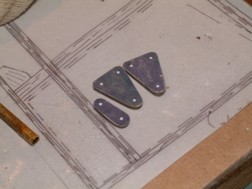
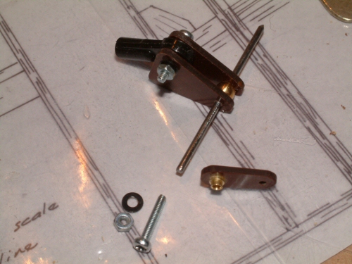
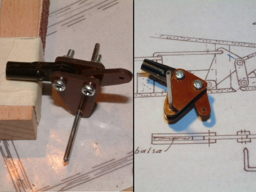
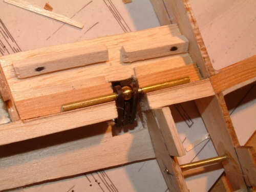
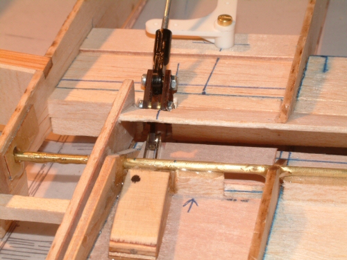
BT uses a linkage system for operating the scale ailerons. I have seen many interpretations by builders who use the same geometry but slightly different design. I will be no different! Pic 1. My design has 2 armatures and one connecting bar. The shapes were cut from Paxolin using a paper template created with Microsoft Power Point. The paper was glued to the sheet for this process. I found it best to cut with a fine hacksaw around the shapes and to finish off with a Dremel and sanding bar to get a clean edge. Pic 2. Assembly shows a ball joint sandwiched between the Paxolin for the bell crank connection, a spare ball at the bottom of the unit to acts as a spacer for the 12 gauge wire baring, and not installed the connecting arm with 2 brass tubes working as a baring. The inner tube is slightly longer to take up the space permitting the outer tube to run freely. Pic 3. The completed unit has no slack across the connections at all and I am relatively pleased with the result. On the plans to show the interpretation. I moved away from bent wire connections as shown on the plans because I always find slack is introduced when using hard materials like Paxolin. Pic 4. Installed into the wing the lower baring will be sandwiched between balsa and just enough epoxy. The ends of the brass tube will be sealed with a spot of Blue Tack to prevent epoxy running into the baring. Pic 5. The aileron connection is completed with a metal clevis secured into a 1/4" ply block. I have also installed a sheet of 1/64" ply to the floor sections of the aileron under the 1/4" ply block to improve rigidity in this area. The plans state 19mm up and 13mm down for the ailerons which is achieved easily, however, the overall down travel is significantly less. I was considering taking action but have decided against it after checking on forums. One oversight is the connection between the bell crank and the ball joint (at the top of the picture) as there is insufficient room for smooth operation. Pic 6. I decided to remount the bell crank deeper into the wing and use an over / under run with the rods on the horns. This gave 2 benefits, 1, the connecting rod movement in the bell crank is smoother, and permits the existing laser cut holes to be used for the connections. |
 |
 |
 |
 |
 |
 |
| 1. Click to enlarge | 2. Click to enlarge | 3. Click to enlarge | 4. Click to enlarge | 5. Click to enlarge | 6. Click to enlarge |
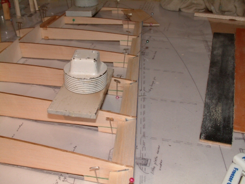
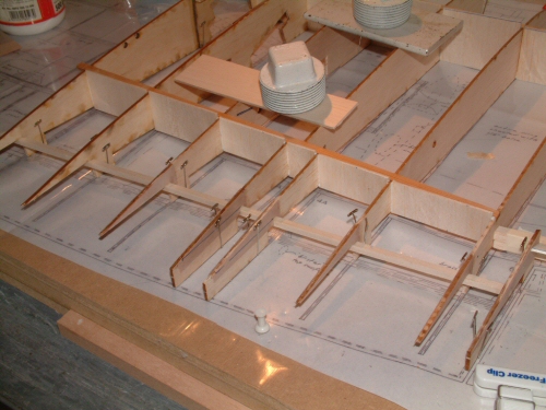
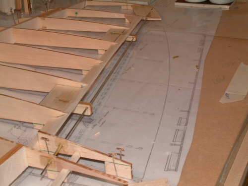
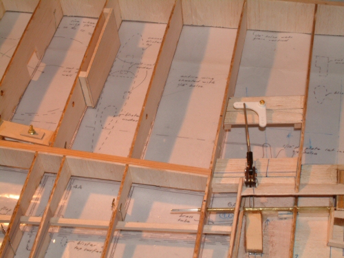
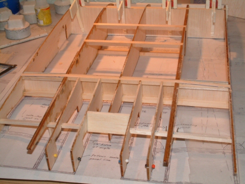
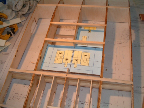
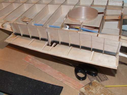
Pic 1. Last thing before I progress to assemble the left wing is the first of 3 front leading edge strips of 1/8" balsa. The remaining 2 strips will be installed much later when the wings have been sheeted. I began construction of the port wing to bring it to the same status as the starboard as in Pic 1. Once the wing could be lifted off the board I started construction of the centre section. Pic 2. First off I connected the 3 inner ribs with spars, having laminated the ply 1B ribs with the 1/8" ply and the balsa doubler beforehand. Pic 3. The plans instruct us to jig the wings in position over the plans and to build the centre section to the wings. This makes rib 1C install at an angle to directly face the root rib of the wing. With my limited space for construction I decided to make a support which took on the same angle as per plans removing the need for the wings to be connected. Pic 4. In use on the first 1C rib. Be careful with the rear spars on the centre section as they will require adjustment to accommodate the floating contours of the "gull" wing. Make reference to the cross section on the plans for details. Pic 5. Progressing with the centre section the 1/6" webs are all in position front and rear. The 1/6" ply in the middle sections of the rear spar fill the entire section. This is a slight deviation from the plans which only specify part of the area to be sheeted with ply. This ply takes the mounts for the wings retaining bolts so I over engineered it you might say! The 2 balsa spars at the rear if the centre section do not meet with the pre cut mounts. I had to cut them in on 2 spars (both sides) to make them fit. I also extended the spar to meet the first rib 1E instead of terminating at 1F as shown on the plans below, no particular reason for this it just felt right! Pic 6. With the centre section assembled I drew plans for the servo installations. There will be 4 in the main area 2 x ailerons & 2 x Flaps and one small servo for the air valve which will be mounted in the wing. After the re-arrangements I had with the Mick Reeves Spitfire I took a lesson from the experience and carefully worked out the positions before committing to any wood. |
 |
 |
 |
 |
 |
 |
| 1. Click to enlarge | 2. Click to enlarge | 3. Click to enlarge | 4. Click to enlarge | 5. Click to enlarge | 6. Click to enlarge |
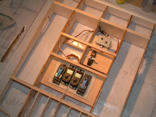
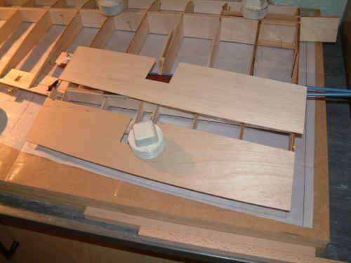
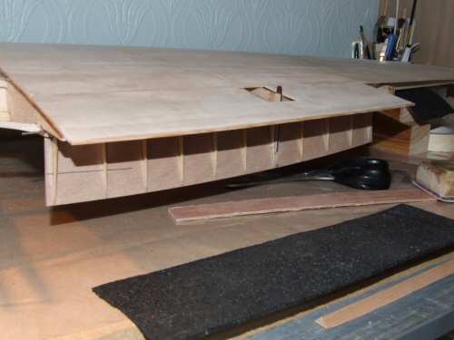
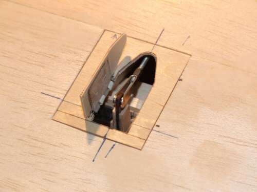
Pic 1. After making the templates the installation of the servo mounts went straight forward. I always mount my servos on light ply sheet doubled with standard ply. Beneath there will be some 1/4" spruce for the screws to fix to. Installation is such that components can be removed should it be required. Note the middle servos will have arms installed to replace the currently seen disks. Pic 2. All connections made to both bell cranks it's time to bring the left wing to the same position. Pic 3. All 3 sections are now complete and ready top sheeting and joining together. Pic 4. Time to give the wing some volume so I started with a general sanding on the upper surface. I decided to make the sheet above the flaps from a lamination of 1/6" balsa and 1/32" ply. The ply gives a great deal of rigidity to the section above the tapering ribs. The cut-out in the middle will hold the hinged door over the landing flap armature which will be added later. Pic 5. Once dry I measured up the top sheeting to the mid point of the main spar. I butt jointed the sheets together on a flat surface before fixing to the wing as seen in the picture, I find it makes for better joints this way. I know salt is bad for you but, along with other household groceries the sheet can be held in position with great affect. Pic 6. The sheeting forward of the main spar was added and allowed to dry before roughly trimming the front face. I forgot to take a picture showing my method for holding the sheet down over the compound curve of the wing, I will try and remember when I sheet the starboard wing! I filled the holes in the sheeting with lightweight filler which were made holding the sheet in position. |
 |
 |
 |
 |
 |
| 1. Click to enlarge | 2. Click to enlarge | 3. Click to enlarge | 4. Click to enlarge | 5. Click to enlarge |
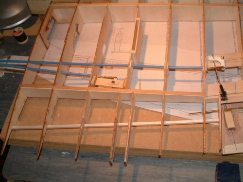
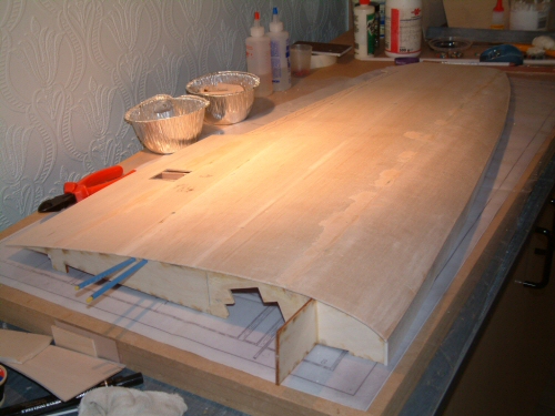
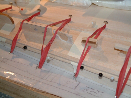
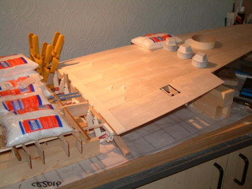
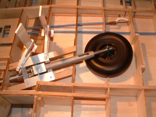
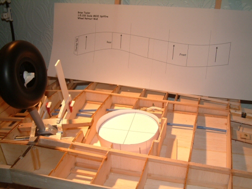
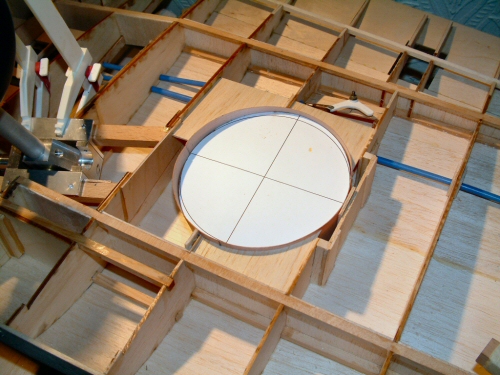
Pic 1. Remembered to shoot a picture of the top front sheet installation. I have found this method puts a uniform pressure on the sheet and holds it nicely in position. Care does have to be taken to install the pins carefully! Pic 2. Installation of the starboard wing to the centre section. I supported the whole thing on wooden blocks and held the dihedral under rib 6 with an extra 46mm on the blocks. I used 12 minute epoxy on the brace and PVA on the rest of the joint. I use a good "flood" of both glues and wipe up the the excess that oozes out if the joints when clamped, after all these joints are the root of the wings strength! Pic 3. Now the wing is connected the 1/2" rails for the undercarriage have been installed and the retract system installed for a test fit. While planning the installation of the rails I built in a space for a "shim" to support the retracts. In the picture I am temporarily using scrap 1/8" balsa for the shims. Later when it comes to final adjustment I will be able to raise or lower the shim to get the exact installation of the arms from ply wood. Pic 4. The wheel wells can be a nightmare. BT does not provide a template for the lining like that provided by Mick Reeves for his 1/6 Spitfire. I re-used an electronic version I had in Power Point and increased it's size to the correct scale. In the background is the template and in the well is the assembled item. Now I have the shape I will cut from 1/64" ply stock and fix into position Pic 5. Ply sheet installed with stiff card lining the inside to hold the shape of the well. It rests on a roll of masking tape for improve stability. I have also installed some 1/16" sheet around the outside of the well walls so the 1/64" ply does not loose shape. This makes sanding and sheeting much easier, with the added bonus of additional strength. |
 |
 |
 |
 |
 |
 |
| 1. Click to enlarge | 2. Click to enlarge | 3. Click to enlarge | 4. Click to enlarge | 5. Click to enlarge | 6. Click to enlarge |
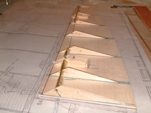
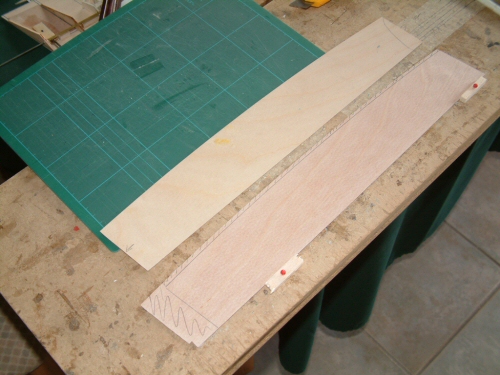
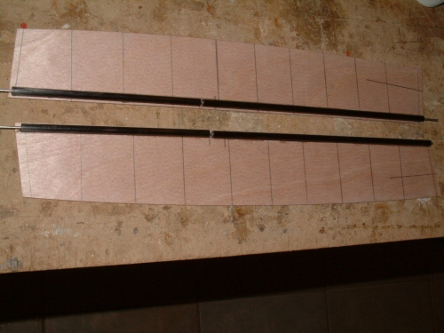
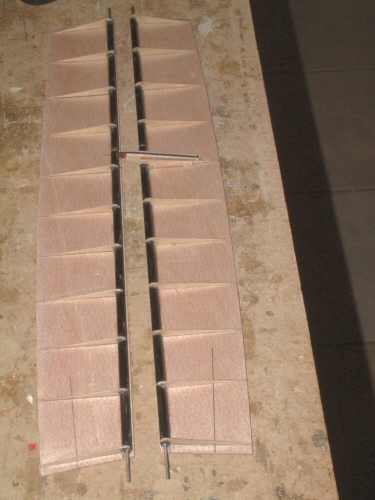
Pic 1. The laser cut 1/32" ply landing flaps are oversized when compared to the plans. In the picture I have one flap cut to the correct size and the second marked ready for cutting. It is a well documented error but never seems to be corrected. First I laminated the sheets with 1/64" ply using polyurethane adhesive. I use this in preference to PVA and other water based adhesives as it tends not to warp as much once dry. Pic 2. The rib positions are marked before affixing 1/4" carbon rod tubing, used in preference to wood dowel. The hollow of the dowel was plugged at all ends and a short length of brass tube installed to hold a wire shaft. A small gap was left part way on each flap to accommodate a mid baring mount as per plans. Pic 3. I cut and installed the 1/32" ply ribs. It took some time to prepare the ribs and to carefully install them in the exact positions. The method I adopted was to put 2 strips of masking tape on the line with 1/32" spacing this was sufficient to hold the ply straight while cyano locked it into position. During all of this process I made sure that the flaps were flat at all times and that I never applied too much pressure. Braking these rules would result in a warped landing flap. This lesson learned from my Mick Reeves build!! Notice also on one flap the Paxolin horn with ply supports has already been installed. Pic 4. The flap is suspended between brass tube cut into the end ribs supported by 1/8" ply bearings at each end to get alignment with the under surface. You may also notice that I have grafted some spruce to the wing trailing edge. This was done to correct a bad measurement by yours truly while installing the top skin! Pic 5. The flap gives full movement with very little resistance, pictured here the flap horn can be seen through the wing skin in the fully down position. Pic 6. The flap armature is covered by a hinged door on the top of the wing. The surrounding frame is from a lamination of 1/32" ply on top and 1/16" balsa underneath. A pocket was made in the frame to hold a nylon hinge which then holds the 1/32" ply door. I will be adding a little hookup on the door to install a return spring at a later date. The frame will be installed now but the door will be installed after the painting process. |
This rebuild has been halted while I get my business establised. It will continue, but I currently do not know when! |