
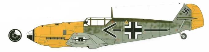
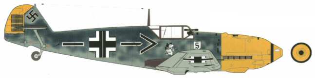
YT International BF109E - FuselageThe all glass fuselage is a big canvas waiting for the adventurous among is to have a go! I am not going to get too carried away with this, nor am I going to major on a particular aircraft. Having looked at a number of colour slides I have decided to blend a few features from various slides that I like, hopefully ending up with a convincing model. Generically it will be a BF 109 E/4 loosely based on the slide below. A good reference book for ideas I found was Scale Aircraft Modeling Colours - Combat Colours No. 1 - Bf 109E. |
 |
 |
 |
 |
 |
 |
 |
| 1. Click to enlarge | 2. Click to enlarge | 3. Click to enlarge | 4. Click to enlarge | 5. Click to enlarge | 6. Click to enlarge |
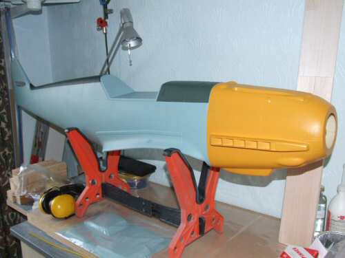
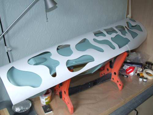
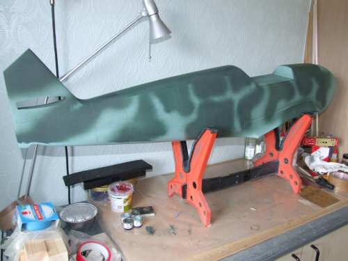
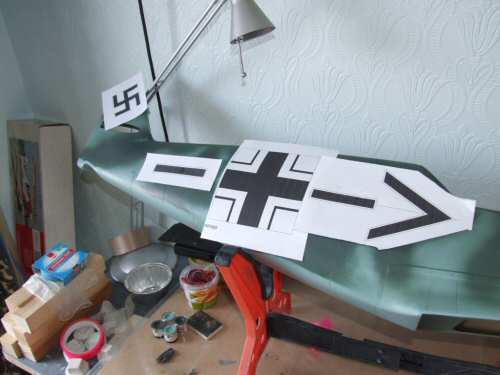
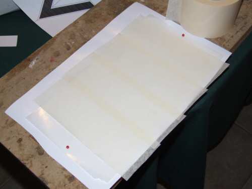
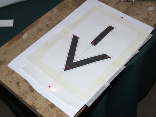
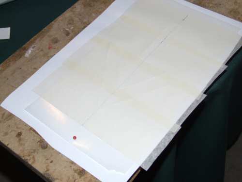
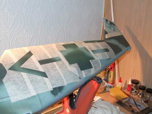
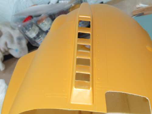
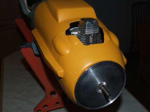
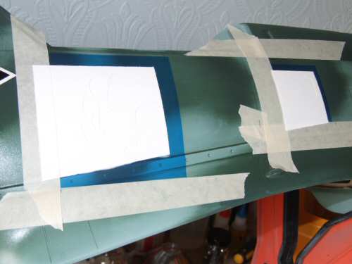
Pic 1. A quick reminder what the model looks like out of the box. On the top there is a small amount of cameo which was typical of the early 1940's. From reference books the cameo is based on 2 colours, which have close Humbrol equivalents. They are Dunkelgrun (dark green) H30 and Schwartzgrun (even darker green) H91. I am going to spray a pattern onto the fuse with a combination of the 2 colours. Pic 2. Rather than spray free hand I made a template to hold in a frame in front of the fuselage. Pic 3. Once dry I ran over the surface with 000 wire wool to scratch the surfaces a little and to level the over spray to ease insignia application. Pic 4. I will be painting the markings so I made accurate templates for the job before making the actual masks. I make masks myself using medium tack wide masking tape, here is a detailed series of slides. Pic 5. The process starts on a building board to which I apply a sheet of stiff card, on top of which I lay a sheet of silicone release paper pinned down. Masking tape is applied in strips with a slight overlap until a big enough area is covered. The masking tape must be wider than the silicone paper so that it sticks to the card. Pic 6. The paper template is pinned to the masking tape and a datum line traced. |
 |
 |
 |
 |
 |
 |
| 1. Click to enlarge | 2. Click to enlarge | 3. Click to enlarge | 4. Click to enlarge | 5. Click to enlarge | 6. Click to enlarge |
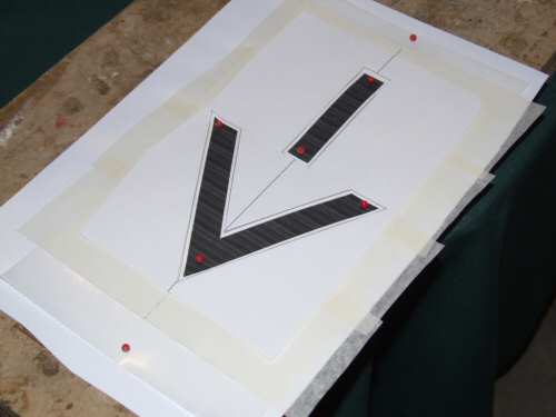
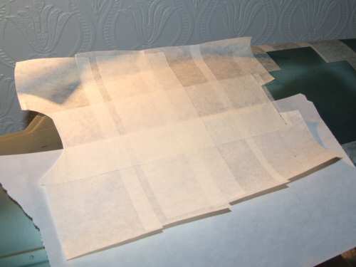
Pic 1. Using a sharp scalpel cut the outline required. Pic 2. Carefully remove the paper template leaving ALL of the masking tape in position, including the cutout area. A second application of overlapping masking tape is applied at 90° from the first layer over the entire mask. This holds the mask steady and prevents the mask distorting during application. Pic 3. The mask is lifted from the silicone paper being careful not to stretch the tape, if necessary cut it away from the card layer. Apply to the model surface with one half masked using a new silicone sheet. this helps align the datum points before the extremities of the template stick down. Once happy with alignment rub the mask down from the centre to the edge over the first half, then remove the silicone paper and wipe down the second half. Pic 4. Carefully lift the top layer of the mask, and then . . . . Pic 5. lift the parts that will be painted. Pic 6. Finished item ready for the white coat application. . . . after I mask the other side that is! |
 |
 |
 |
 |
 |
 |
| 1. Click to enlarge | 2. Click to enlarge | 3. Click to enlarge | 4. Click to enlarge | 5. Click to enlarge | 6. Click to enlarge |
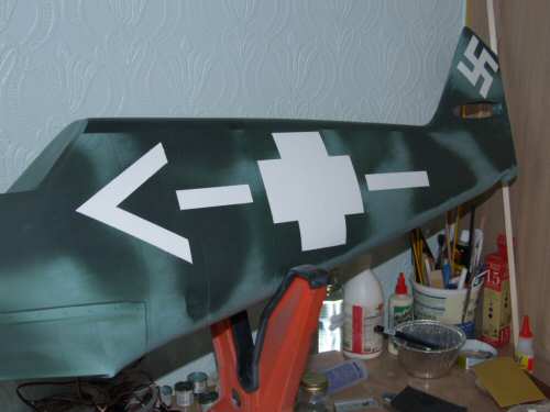
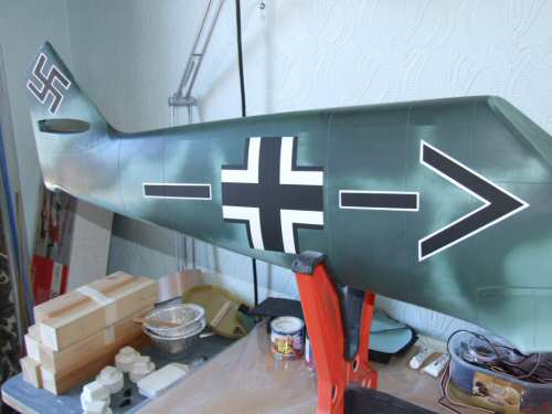
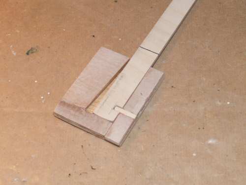
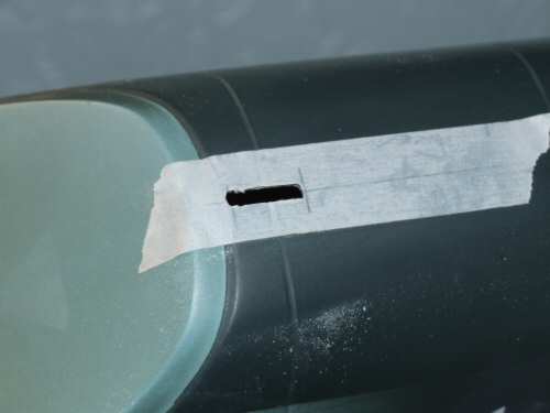
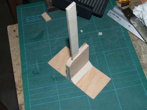
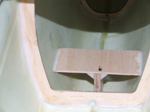
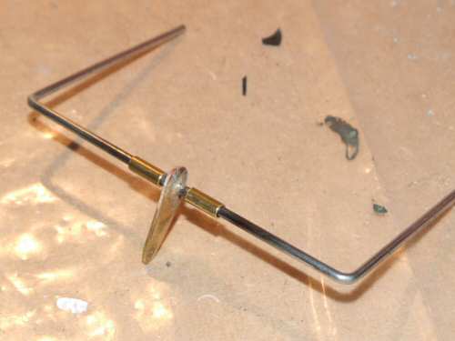
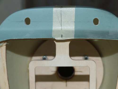
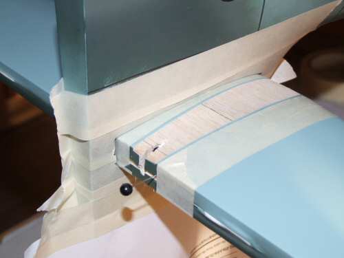
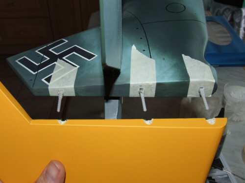
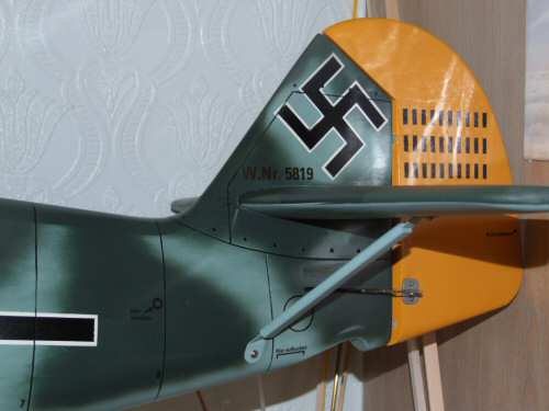
Pic 1. With the white applied I will permit the paint 2 days to harden before I re-mask and paint the black over with a new set of templates. I will rubdown the edges with 000 wire wool first to wear down the edges before masking. Pic 2. Second colour and the result is reasonably OK, one or 2 small errors but the weathering will hide them sufficiently. Pic 3. The kit does not include a radio mast for the 109, a feature which for me needs to be included, even with this semi-scale model. I use the same technique as for previous models, a slide in setup for the 1/8" ply that locks in position when pushed back (aft). With the antenna up and swung between the mast and the fin the tension will prevent the mast from sliding out. Pic 4. A slot is cut in the fuselage slightly rearward of the correct scale position as I don't fancy playing with the canopy. Pic 5. Before assembly as shown here the unit was test fitted dry to ensure the mast was held vertically before committing the adhesive. Pic 6. Installed with epoxy and microbaloons mix. The arrow is to remind me which way is forward :) |
 |
 |
 |
 |
 |
 |
| 1. Click to enlarge | 2. Click to enlarge | 3. Click to enlarge | 4. Click to enlarge | 5. Click to enlarge | 6. Click to enlarge |
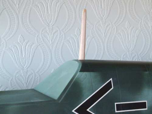
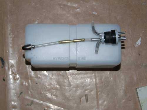
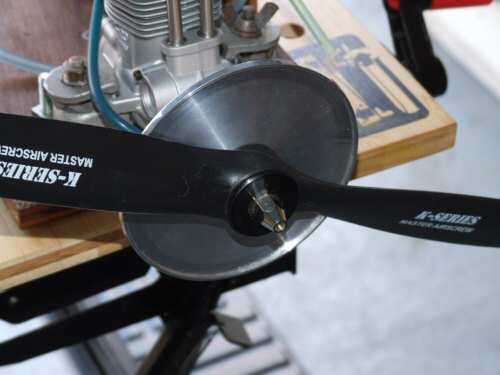
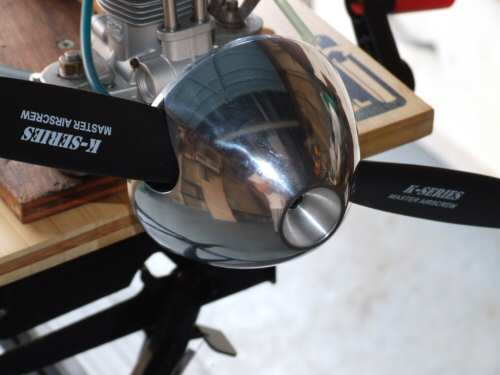
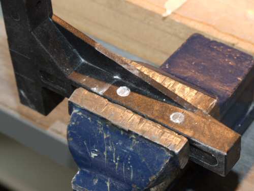
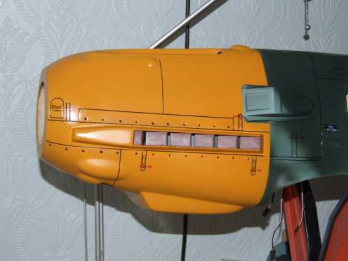
Pic 1. Once installed I sandwich the 1/8" ply with stiff 3/32" balsa and sand to shape. I will seal with glass and install a linkage for the antenna later. Pic 2. In the rush to put the "Geschwader Kommodore" marks on I noticed I had messed the point on the front bar. I was not bothered for a while but decided to correct the error of my ways. Pic 3. Decided to put the fuel tank together with the stock supplied parts. Went together nice 'n easy. When I tested it for leaks in my sink there were no leaks on the first test - unusually good for me to get a pass on the first attempt! Pic 4. The spinner needs above average consideration as the sunken head creates a smaller cavity to fit everything in. The kit comes with a shim adaptor to space off behind the spinner to make the shaft shorter. I was able to install the unit without the spacer using a Master Airscrew 15 x 8, washer, and cone adapter. It was only necessary to shorten the cone adapter by 5mm. Final result is shown in the picture which has plenty of thread remaining to hold the prop in position. Pic 5. A shortened M4 bolt finished the job off. Pic 6. First job with the cowl was to cut out the exhaust. This will provide some good exit points to help cool the motor. |
 |
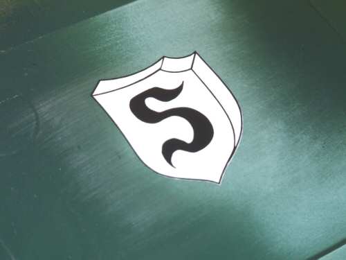
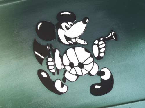
| Having looked around at more schemes and taking on board what I have already completed I thought I would make the model a bit more of a mix and add markings for Adolf Galland who was a very successful, and highly decorated fighter ace with 100+ kills. Galland was Gruppenkommandeur of III/JG26 at the beginning of the Battle of Britain. I Liked the look of his "Mickey Mouse" type cartoon he used :) |
 |
 |
 |
 |
 |
 |
| 1. Click to enlarge | 2. Click to enlarge | 3. Click to enlarge | 4. Click to enlarge | 5. Click to enlarge | 6. Click to enlarge |
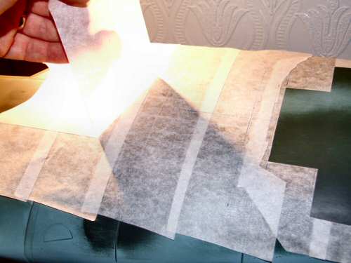
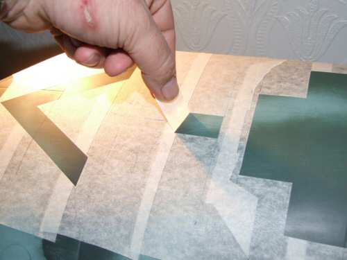
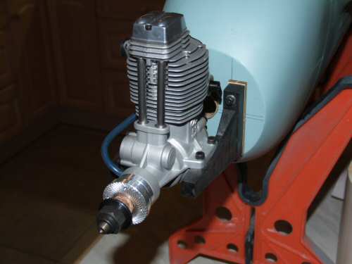
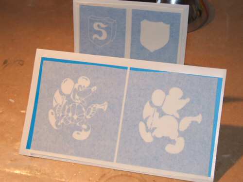
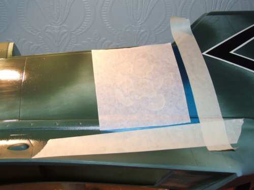
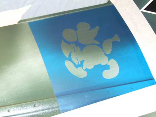
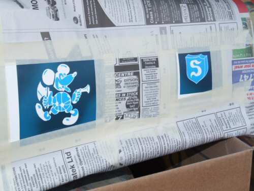
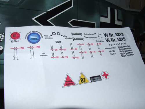
Pic 1. I measured the mounts to get the 148mm from firewall to prop plate. I always drop a few millimetres from the measurement, working on the theory that it is easier to shim the mounts compared to re-drilling, sanding etc. A tip I got from RCMF forum was to put the engine over the mount, dust talc over the mount and then remove the engine. Easy to see holes! Pic 2. Engine mounted, and after all the measuring it is short by 4mm (2mm more than theoretical) so will need 2 ply shims, which are supplied in abundance with the kit. Pic 3. The engine mounted in position with the cowl & spinner base plate located. The engine could do to be a little lower in the mounting, so it will receive 2mm of shim on the engine beams if required at a later date. Pic 4. With the engine sorted I removed the engine for safety while I continue decorating. I was going to have a go at painting the mouse on the side of Galland's 109. From the RCMF forum I bumped friend who very kindly produced the Galland markings using his plotter cutter. There are 2 plates for each item first the white, then the black. Pic 5. In preparation I have peppered a gloss polyurethane coat to the application areas on the fuselage to ensure a good seal for the mask. Masking tape sets the guide lines for the masks. Pic 6. The front "application sheet" is removed once the stencil is in position. |
 |
 |
 |
 |
 |
 |
| 1. Click to enlarge | 2. Click to enlarge | 3. Click to enlarge | 4. Click to enlarge | 5. Click to enlarge | 6. Click to enlarge |
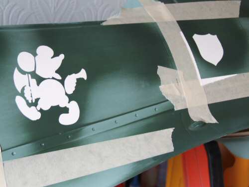
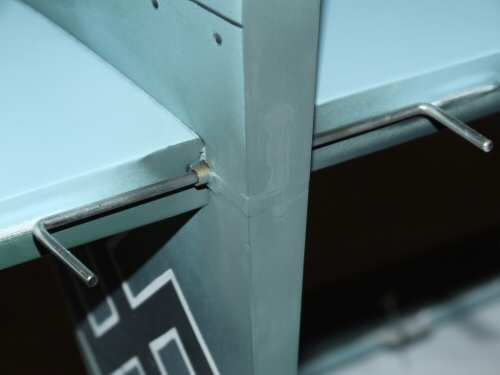
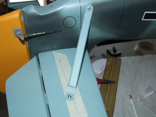
Pic 1. This picture was taken after all other protective masking was removed prior lifting the actual masks. I built several layers of paint up slowly. Pic 2. The mask was removed after an hour revealing a nice result. I will rub it down with fine wire wool again before the next coat to remove any lips on the paint edges. Pic 3. The last masks applied with great care ready for spraying. Pic 4 & 5. After 4 light coats the masks were removed revealing a good result. Some "gum" from the masks remains on the white surfaces, but that will be removed much later when the paint is fully cured. This side had the best results, on the other side there was a bit of poor alignment on my behalf which exposed more white shadow in the edges. Pic 6. now the basic fuselage is ready I moved to the control surfaces starting with the elevator. I wanted to hide the controls for the elevator so I fabricated a wire brace to connect the 2 elevators together and carefully silver soldered a brass horn to fit inside the fuse. Notice also 2 short length of brass tube which will be used to make a small baring in the stab's skin. The horn is set at an angle to get the best range of movement from the rudder up and down without hitting the rear infill for the rudder. Before I install the horizontal stab I decided to get the wing ready and fully seated in the fuselage to assist in alignment. |
 |
 |
 |
 |
 |
 |
| 1. Click to enlarge | 2. Click to enlarge | 3. Click to enlarge | 4. Click to enlarge | 5. Click to enlarge | 6. Click to enlarge |
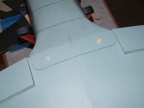
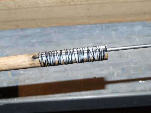
Pic 1. My measurements for the wing dowel's was a little out! fortunately I was able to file them out to the correct point without suffering any movement in the wing. Pic 2. The rear brace was installed onto the wing and the mounting holes drilled with great care to get the correct angle. With the wing now mounted and considered true I continued with the horizontal stabiliser. Pic 3. I masked the surrounding painted areas and cut the Solartex from the stab as instructed. I took time to ensure everything was true before fixing into position with 12 minute epoxy. I made several measurements to make sure the fitting was true. Excess glue was removed immediately but the tape remained until dry so as to minimise movement. Pic 4. Once dry I too my trusty Dremel and cut into the back of the vertical stab to make provision for the hidden linkage. Once done I began fabricating the control rods. Pic 5. I don't see a problem using the stock dowel system, it has been used for many years and is well able to manage the loading produced by this size of model. I do however groove the wood to make a channel for the rod to fit into, wrap it in nylon thread soaked in Aliphatic glue as seen in the picture before using the supplied heat shrink (after it's dry). Pic 6. All patched up after installation of the torque bar. |
 |
 |
 |
 |
 |
 |
| 1. Click to enlarge | 2. Click to enlarge | 3. Click to enlarge | 4. Click to enlarge | 5. Click to enlarge | 6. Click to enlarge |
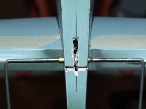
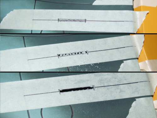
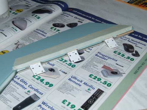
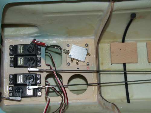
Pic 1. The rudder was installed using the pin hinges provided. For the middle and lower pins I installed extra material inside the fin to provide more grip to the pins. Pic 2. The rudder push rod comes out of the side of the fuselage. Before you cut this hole install the horn in the rudder to make sure it is installed in the hard solid section at the bottom of the rudder. Top picture shows the line of the cut which will open out to 3mm. Middle picture, drilled out with 2.5mm drill down the middle, and finally the bottom picture shows the slot opened out with a fine file. When filing be sure to only apply pressure as you push the file inwards. To do so as the file is withdrawn could cause the paint to splinter! Pic 3. The elevators will be installed using standard pin hinges, in this case Kavan branded. 12 minute epoxy was used to permit timely installation. Pic 4. The elevator stabilisers installed without any issues, but I did find it a better fit by installing a little closer to the trailing edge than specified. The line on the masking tape is set at the specified 40mm. Pic 5. The throttle will be controlled via a bell crank installed on the engine mount, this permits 2 straight connecting rods to be installed. Pic 6. In the fuselage the connections were all made except for the power switch, air lines, and air filler line. I have still not decided where to put them so I will work on other things until I have decided! |
 |
 |
 |
 |
 |
 |
| 1. Click to enlarge | 2. Click to enlarge | 3. Click to enlarge | 4. Click to enlarge | 5. Click to enlarge | 6. Click to enlarge |
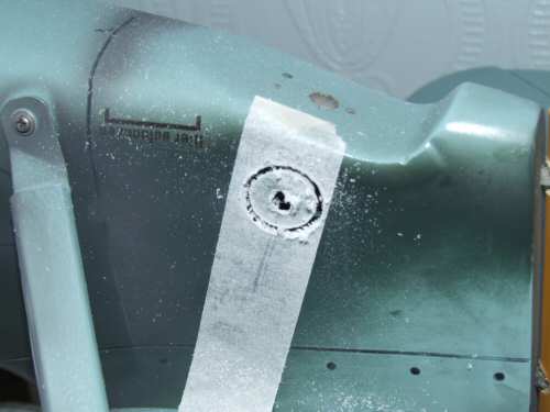
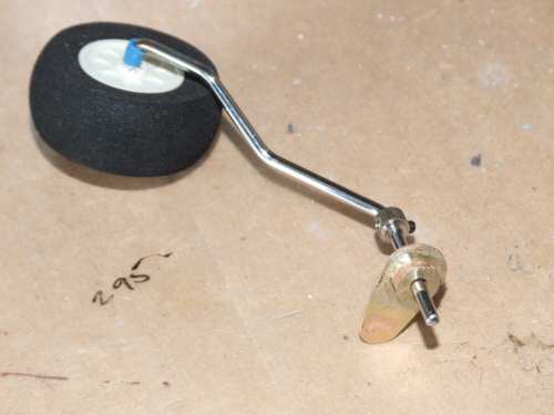
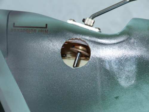
Pic 1. Getting some extra detail I produced some water slide decals for the job. I have not gone overboard, just the main decals. Pic 2. The water slide decals need a gloss finish for good adhesion so I sprayed the necessary areas with gloss Polyurethane before applying the decals. The fill flashes were added using a paint mask. Pic 3. Highlighting detail with the permanent pen again and the water slide decals to finish it off. Pic 4. I have put off installation of the tail wheel for as long as I can! Not wanting to route the external horn externally via the rudder I decided to make it fully internal. I first needed to cut an inspection hole in the side of the fuse. I did this with a 20mm circular cutter. Pic 5. Next I fabricated a new brass horn and silver soldered it to a brass wheel collet. Pic 6. Installation order was to insert the shaft, followed by the new horn assembly securing it via the inspection hole. The push rod will be a plastic "snake" affair secured at 3 points along it's route for stability. The hole will be sealed using aluminium tape so that weight is minimised and easy access is possible should it be necessary. |