
Mick Reeves 1/6 Scale Spitfire Review |
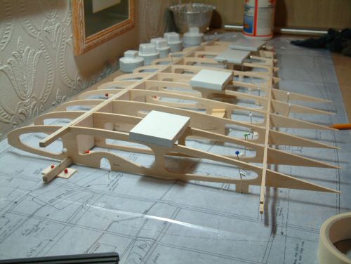
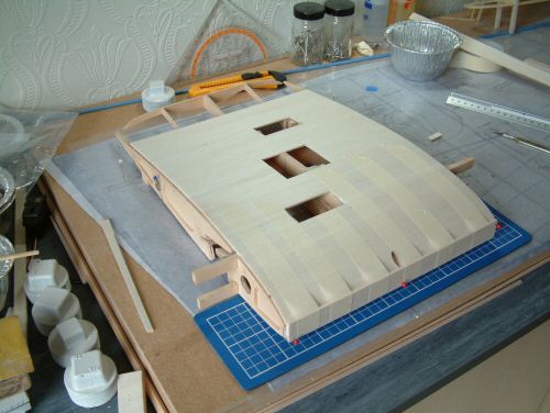
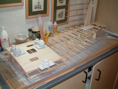
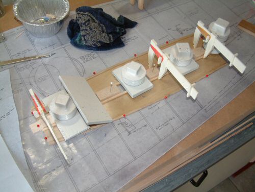
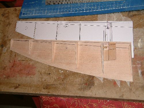
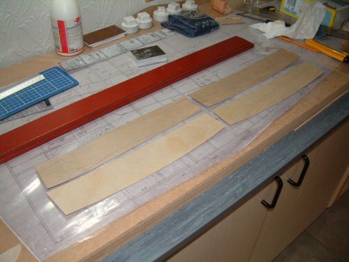
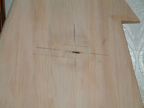
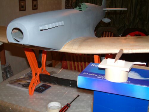
| The wings are pretty much standard construction (for a Spitfire that is) with a centre section and 2 main runs joined with a 4" dihedral on each wing. Before starting with the build I had to check all the parts on the plan to correctly identify each part. I marked all ribs to identify them and dry fitted as many times to be sure all would go together without any hitches. |
 |
 |
 |
 |
 |
| 1. Click to enlarge | 2. Click to enlarge | 3. Click to enlarge | 4. Click to enlarge | 5. Click to enlarge |
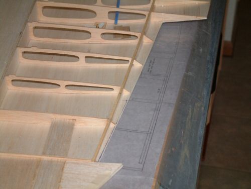
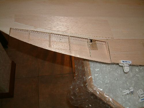
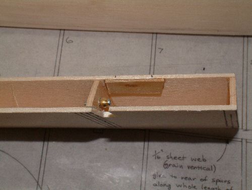
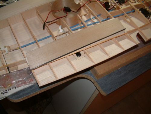
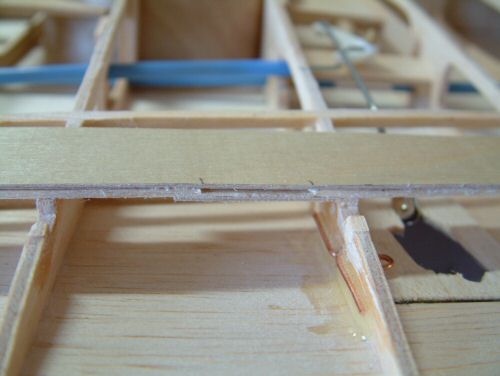
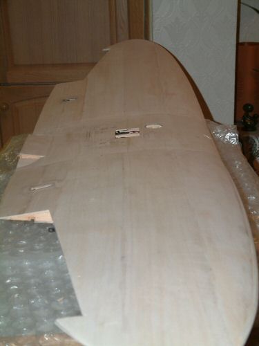
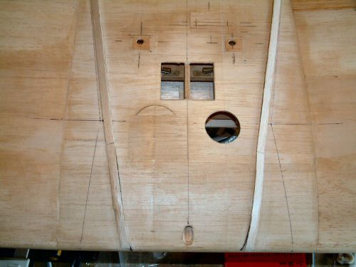
Instructions are a bit thin on the plans for the wing build so I dry assembled the wing first to ensure I was getting the drift. Pic 1 & 2. The front 1/4" balsa spar rests on scrap 3/32" while the rear end is supported by built in tabs on the ribs. I found some ribs needed a touch extra support under the rear tabs to maintain alignment of the neighbouring ribs (W4 & 7). When fitting the lower rear 1/8" spars alignment in the aileron area was very poor and some ribs required trimming to make the spar fit straight as shown on the plans. I then installed the 1/16" webbing,wing tips, aileron and flap crank mountings. Be careful with the wing tips as the slots in W15 need to be increased as they are not positioned correctly to receive the wing tip balsa sheet as shown on the plans. Pic 4. Servos will be mounted as shown, 2 servos for ailerons, 1 for the flaps and 1 for the retract servo. I am using Futaba S3004 servos for all jobs and the Futaba S136G retract servo. Pic 5. Sheeted and first of 2 1/8" leading edges in position. |
 |
 |
 |
| 1. Click to enlarge | 2. Click to enlarge | 3. Click to enlarge |
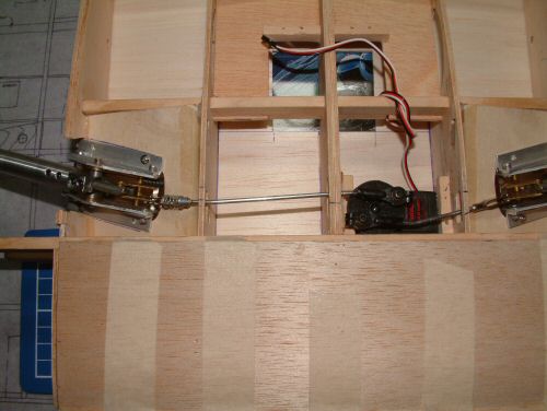
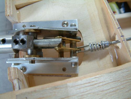
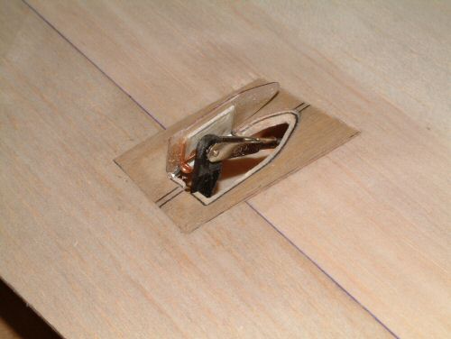
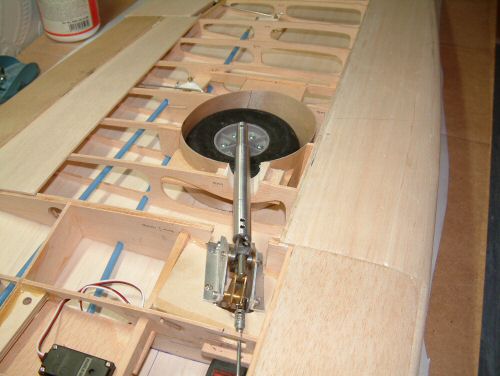
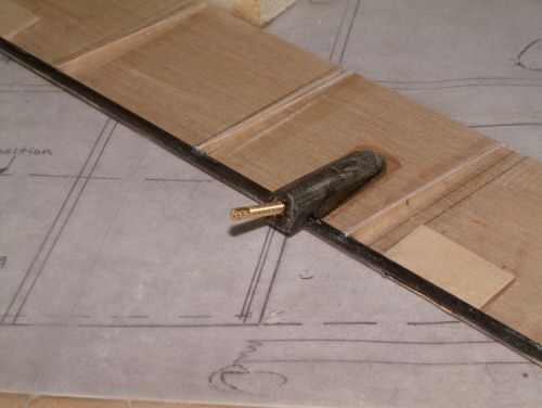
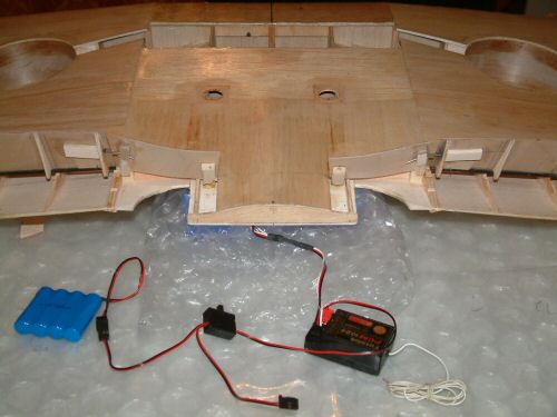
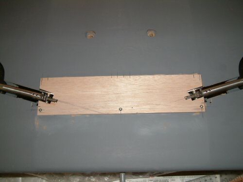
Everyone hates setting up retracts, but they have to be done. I thought I would get the basic operation working before fitting the wings etc. Pic 1, The travel on the servo needs to be 22mm from end to end so I drilled just short of 11mm from the centre of the servo disk. Because of the angle the retracts are mounted at easy connection was hindered by the proximity of the mounting plate to the clevises when the wheels were retracted. Maintaining the bends to a minimum was challenging, but possible. Pic 2, Modest holes were needed to ensure jam free operation of the rods. Be careful of the mounting plates, some sanding will be necessary to ensure free operation. Pic 3, close up of retract unit. Note corner cut from the wheel rod so that the clevis does not catch as it passes. The plans tell you to cut the clevis, but I can't see any problems cutting the side from the rod. The Futaba S136G retract servo has 5.5 Kg/cm power, which when tested, proved to be just able to make the wheel units move. I decided that the best way forward would be to scrap the Futaba unit and purchase the Reeves retract motor. I continued with the build while waiting for the motor. |
 |
 |
 |
 |
| 1. Click to enlarge | 2. Click to enlarge | 3. Click to enlarge | 4. Click to enlarge |
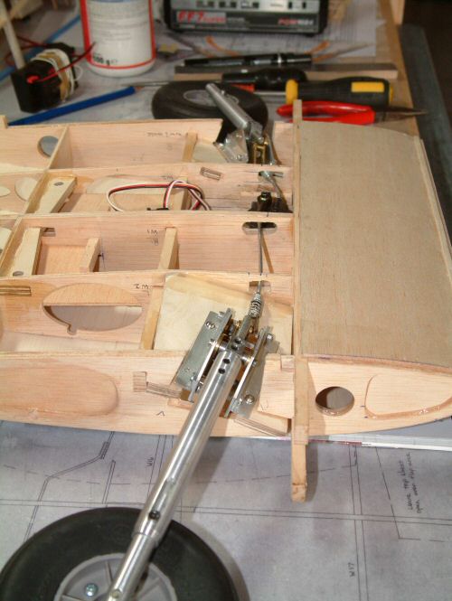
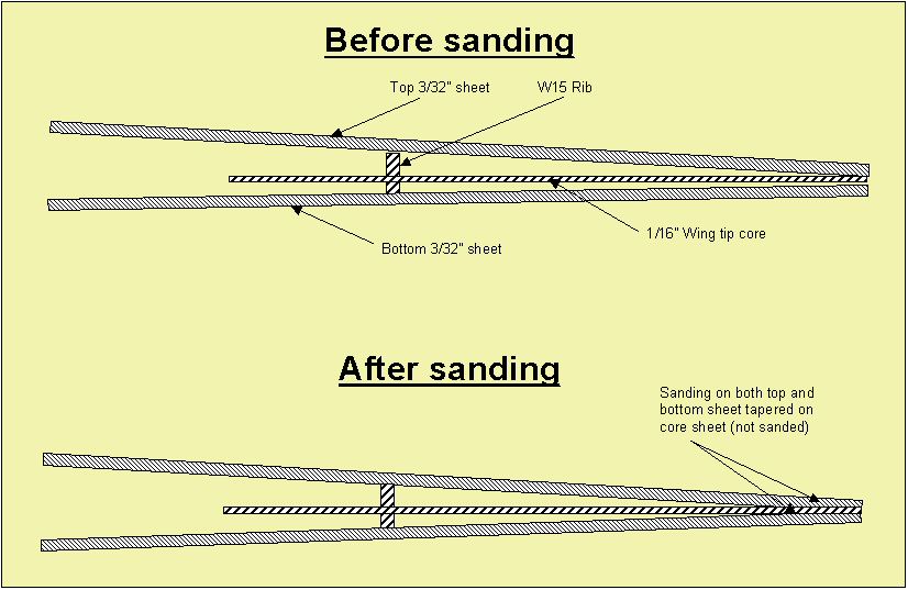
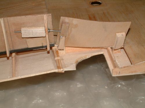
Now the retracts are working I have taken out the mechanical parts to fix the wings. Pic 1. shows the right wing in position held at 4" dihedral. I used 30 minute epoxy for this job just to be sure I had plenty of time for adjustments. Once dry I made the holes for the control rods to fit down the length of the wing. Pic 2. Finally (and much later) the lower sheet will be installed after all the internals are in position. Pic 3. Shows the first of two 1/8" strips for the leading edge in position. The second was applied much the same way. Pic 4. Schematic of sanding at wing tips before gluing wing tips. |
 |
 |
 |
 |
 |
 |
| 1. Click to enlarge | 2. Click to enlarge | 3. Click to enlarge | 4. Click to enlarge | 5. Click to enlarge | 6. Click to enlarge |
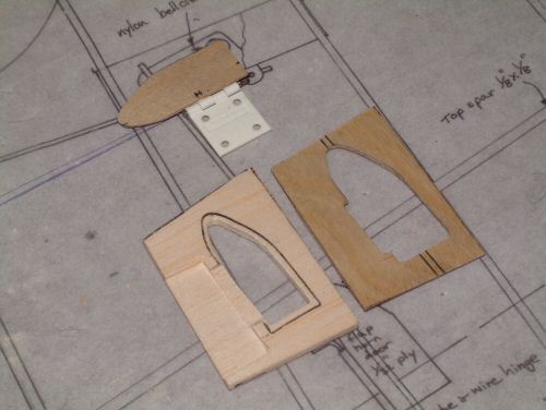
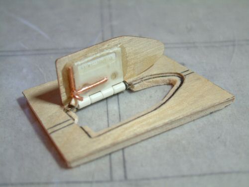
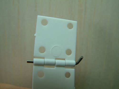
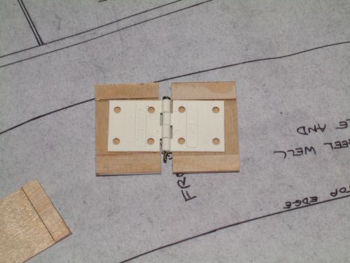
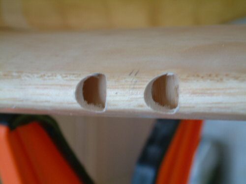
The flaps are made from 3/32" ply and a length of 5/16" dowel. Pic 1. shows the dowel glued with epoxy resin to the dowel. There are 2 parts to the flaps, an outer and an inner. For now I am only going to concentrate on the outer section. The inner section will be installed when I get the wing fitted to the fuselage so I can ensure the contours of the underside are followed. Pic 2. Control horns are made from bell cranks supplied in the kit trimmed as shown. The wing is very thin at the trailing edge and the flap horn will pass through the top skin when operated. I was considering an alternative fitment to save having to put a hole in the top wing but discovered that this was how the real Spitfire flap mechanism operated so I persevered with this design. Pic 3. The wing door parts made from sheet 3/32" ply and the lower support from 3/16" balsa. A shortened standard hinge is used to support the small door. I built it this way so the door can be installed after the model is painted. Pic 4. The assembled unit including a hook point to connect elastic to hold the door closed. Pic 5. The completed unit installed and connected. Pic 6. shows the flap in position and a groove cut out of the wing ribs to accommodate the dowel. A good tip while fitting the ribs on the flap is to wedge some 1/16" balsa under each end and to weight the middle down. This introduced a slight curve into the flap to ensure the flap fitted flush to the wing when closed. See later these flaps were rebuilt slightly different - click here |
 |
 |
 |
| 1. Click image to enlarge | 2. Click image to enlarge | 3. Click image to enlarge |
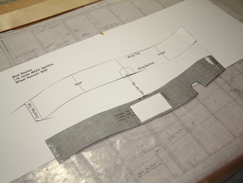
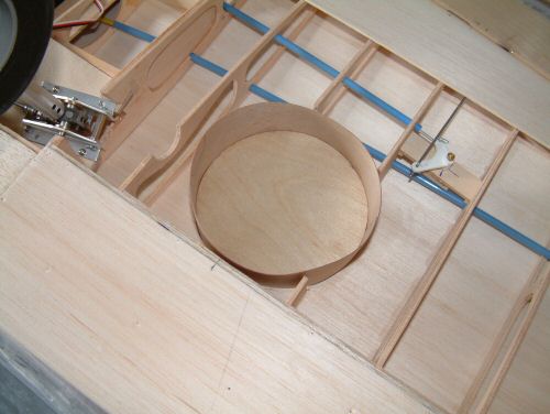
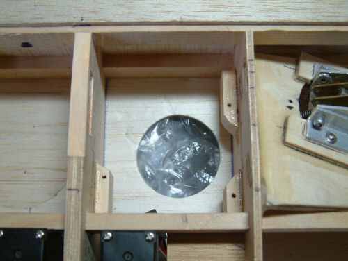
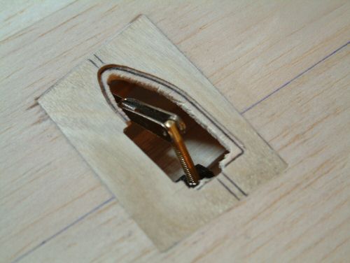
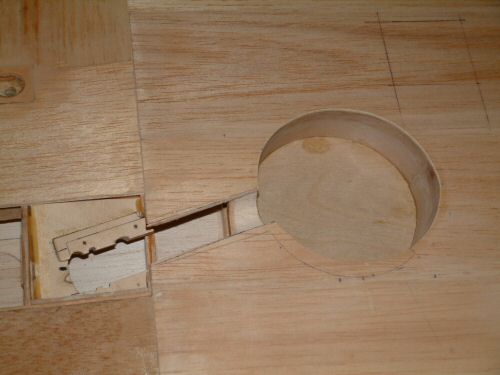
The plans suggest the wheel well liner should be fabricated from cardboard. I decided to use 1/64" ply and to install before the lower skin is fixed. Pic 1. The template on the plans was not quite right so I knocked one up on Power Point for my own use. Pic 2. The underside of the wing was sheeted with a 1/32" ply liner 111mm in diameter. I then installed the well. Because of the odd angle the wheel exits from the wing the well is not a straight hole and moves forward towards bottom of the wing. I also installed some support for the well and tidied up some ribs that I had to trim heavily to get the liner in. Pic 3. &shows the installed well with the wheel located. It is also possible to see the angle of the well from this picture. |
 |
 |
 |
 |
 |
| 1. Click to enlarge | 2. Click to enlarge | 3. Click to enlarge | 4. Click to enlarge | 5. Click to enlarge |
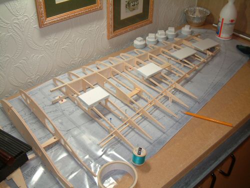
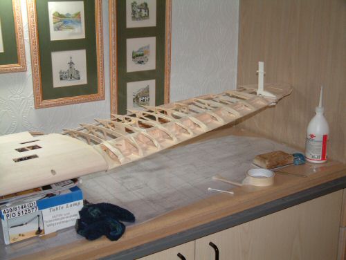
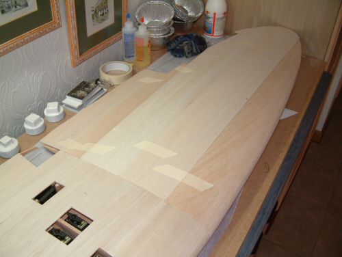
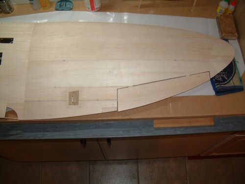
Time now to get the second wing installed. Fitted as the right hand but taking care that the wings are in alignment. Pic 1. shows the installed wing and the front bottom leading edge held in position while drying. After adding the top front sheet and the 2 x 1/8" leading edges I prepared the top sheet. I didn't take any pics of this process for the R/H Wing so I remembered to snap some this time. Pic 2. Shows the individual strips in position taped together. I mark each joint with a line so the alignment can be reproduced. Pic 3. The sheet is removed from the wing and glued before laying down on the pinning board with metal weights to ensure it remains totally flat. The tape is not removed between sheets from the dry fit to ensure total alignment. Pic 4. The nice thing about building in the kitchen is the availability of weights to hold the sheet down while drying :) but seriously, I was very careful to ensure the wing was fully supported and resting correctly on the building board before adding the weights Pic 5. The tail end of ribs in front of the ailerons required extensive trimming to permit sufficient movement of the ailerons which were to be installed next. |
 |
 |
 |
 |
 |
 |
| 1. Click to enlarge | 2. Click to enlarge | 3. Click to enlarge | 4. Click to enlarge | 5. Click to enlarge | 6. Click to enlarge |
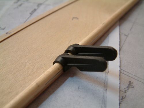
The aileron are constructed from some ply ribs sandwiched in 3/16" balsa. Pic 1. The hinges suppliedare made so that the pin can be removed for service work etc on the model. I decided not to use them, not for any particular reason, but I did use similar hinges with fixed pins. Pic 2. Hinges were to be mounted inside sleeves made from 1/32" ply. Construction is straight forward, although one of the pre supplied ribs (W12) was slightly longer than required and needed a little trimming. Unfortunately the ailerons had to be re-built when I found they were not deep enough nor long enough. Tip: I really recommend you build the whole wing before building the ailerons. If you don't then you'll run the risk of a poor fit in terms of depth and profile along the training edge. I actually built the ailerons a third time when the wing was finished because I was not happy with the profile at the training edge of the second pair! Pic 3. Aileron base and the deeper ribs in position. Note also the pre installed brass ball joint for the control rod which was bolted in position and locked with cyano. A small section of 1/32" ply was laminated on the inside of the aileron bottom sheet surrounding the opening for the ball joint. This will give some protection from the knocks it is likely to receive while connecting and disconnecting the socket from the ball. Pic 4 . Installed the aileron into the wing and held in position with clips and pins underneath to hold in position. The top sheet was installed with the aileron in the wing. This permitted constant checking of the alignment and profile. Pic 5 . Aileron removed after marking hinge points and sleeves mounts installed according to location marks with cyano. The face sheet was then added to the ailerons and sanded to shape. Pic 6. the other aileron was produced in the same way. In this picture the sheeted wing and aileron were not sanded to shape. |
 |
 |
 |
 |
| 1. Click to enlarge | 2. Click to enlarge | 3. Click to enlarge | 4. Click to enlarge |
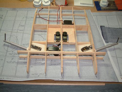
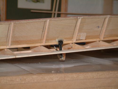
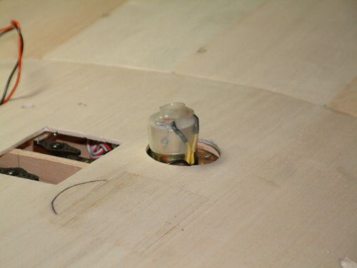
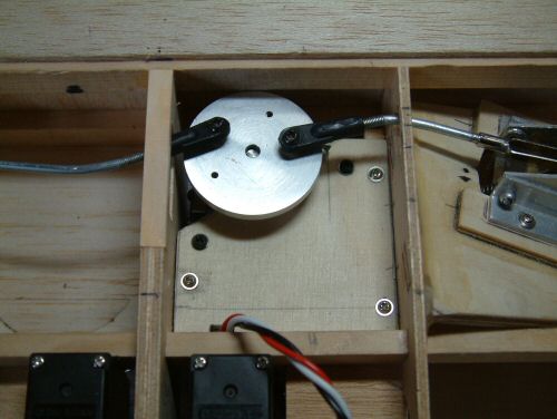
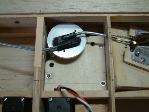
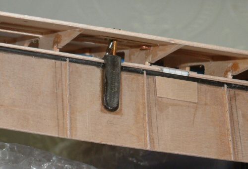
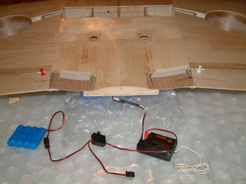
I have started with the replacement retract servo. Firstly I stripped the original Futaba unit out of the wing and installed the servo in the same section. This proved to be a mistake when considering the rotation of the servo and it's restricted position in relation to the retract mechanisms. Pic 1. shows the new servo mountings on the correct side according to the instruction sheet supplied with the kit, which is to the left of the centre section (picture viewed from bottom). The servo was mounted on a sheet of ply and fastened to the mounts with screws. Pic 2. shows the motor protruding out of the upper wing section. You can also see my patchwork on the sheeting following relocation of the servo. Pic 3. Here is the servo position with the wheels fully retracted. Note the 2 additional holes from failed installation in right section. The instruction sheet shows how to stagger the mounting of the ball joints to get one wheel traveling out of sync with the other as with real spits. I followed the instructions being careful to ensure the radius of the mounting was 11mm or 7/16". Pic 4. Servo position with the wheels in the down position. Just aligned nicely. Follow the instructions, make sure you do a dry run and everything will be fine. I am very impressed with this gear motor, delivering 45Kg/cm compared to the Futaba 136G's measly 5.5 Kg/cm it had no trouble raising and lowering the wheels over a graceful 5 second period. |
| |
 |
Video of the final setup with the Mick Reeves Retract servo. This video is in my video section hosted by YouTube |
|
Front view (206Kb) |
| At this point in the build I was becoming concerned about the landing flaps. The flaps do not go to the trailing edge of the wing as I believe they do on a genuine MK IX Spitfire. More importantly they do not operate as smoothly as they should, particularly when closing. The single servo is chattering a little and I do not like to hear this noise when the model is static with no loads. I decided to rebuild the flaps slightly different to plan. |
 |
 |
 |
 |
 |
 |
| 1. Click to enlarge | 2. Click to enlarge | 3. Click to enlarge | 4. Click to enlarge | 5. Click to enlarge | 6. Click to enlarge |
The new flaps will be built differently and run to the training edge so I am starting with the wood oversized to get the cut correct when the flap is mounted on the hinge. Pic 1. Laminating 1 x 1/32" and 1 x 1/64" ply wood which will be held very flat with steel bars (in red) for 24 hrs while drying. Absolutely vital to ensure the flaps are flat for good fitment at the trailing edge. Plans show just 1 piece of 1/32" ply with strip on trailing edge (see previous build). Pic 2. shows a length of fibre tube epoxy glued to the front edge which will hold the edge very straight. Pic 3 . In an effort to align the hinge point on the flaps at 1/32" (cut with a Dremel grinding wheel) I have replaced the hinge point on the wing with a laminate of 1/16" balsa sanded out to accept the hinges where needed, and then covered by 1/32" ply. This puts the hinge point in perfect alignment. Pic 4. is my version of a control horn fabricated from laminate plastic and brass horn. Pic 5.the installed item with the flaps in the "up" position. Pic 6. Flaps at 85° as per plans showing the hinge installation and the control horn. This arrangement runs a little more smoother than the original installation and I am relatively pleased with the setup. |
 |
 |
 |
 |
 |
| 1. Click to enlarge | 2. Click to enlarge | 3. Click to enlarge | 4. Click to enlarge | 5. Click to enlarge |
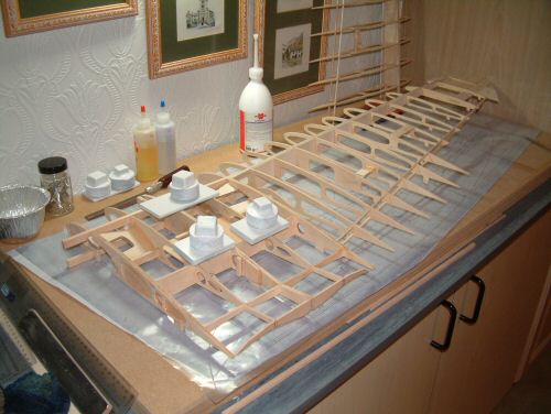
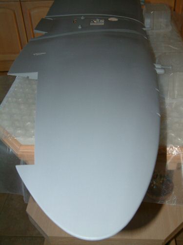
Having worked on the fuselage for some time I returned my attentions to the wing. Re-visiting the installation of the Flap servo operating the 2 bell cranks, I decided to abandon this method in favour of 2 small Hitec servos I had spare. They will be connected via a "Y" cable and one servo was "reversed" to enable mirrored installation in each half of the wing. Click here for information on reversing servos. The redundant hardware was removed to make way for the new installation. Pic 1. Shows the right wing refitted with the mini servo connected directly to the flap push rod. This works far better and I strongly recommend this type of installation to all builders. Pic 3. The completed wing after the first all over sanding. I installed the ailerons every now and then to ensure the profile could be followed. Some areas needed light filler before the final sanding. Pic 4. shows the first application of the bottom right wing overlapping the entire centre section of the wing. Pic 5. The bottom left was also made to overlap the entire centre section. This gives a good covering and an easy edge to feather away the glass ridge. |
 |
 |
 |
 |
 |
 |
| 1. Click to enlarge | 2. Click to enlarge | 3. Click to enlarge | 4. Click to enlarge | 5. Click to enlarge | 6. Click to enlarge |
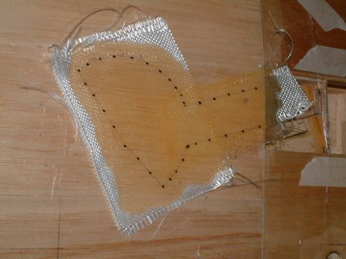
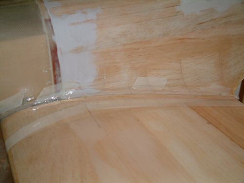
Other Tasks for the wing were the preparation of the wheel pants. Pic 1. I made castings of the wheel pants roughly to shape before cutting the wheel well . . . Pic 2. and sanding to shape. The joint with the wing sheet was wiped over with a coating of epoxy to add some strength to the sanded edge Pic 3. The side fillets on the wing root to the fuselage were also prepared. Pic 4. shows the alignment of the fuselage on the wing. I carefully masked the area to prevent the wing sticking to the fuselage. After installing the fuselage I ran a strip of tapered 1/16" sheet close to the seating of the fuselage with Epoxy. When set I smeared a thin coat of Epoxy mixed with Microballoons over the surface to smooth the round of the fillet. Pic 5. Wing removed and the fillet exposed. Pic 6. In preparation for the installation of the Cannons I cut the holes for the cannon and the blanked cannon. |
 |
 |
 |
 |
 |
 |
| 1. Click to enlarge | 2. Click to enlarge | 3. Click to enlarge | 4. Click to enlarge | 5. Click to enlarge | 6. Click to enlarge |
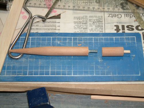
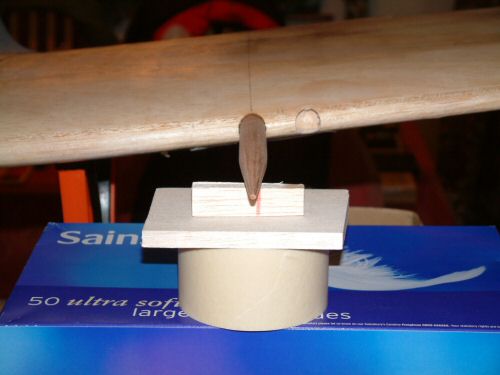
Pic 1. The Hispano Cannons are fabricated from solid 16mm Beach Wood with a threaded insert. These were produced on a wood turning lathe via a friend of my Dad. Pic 2. They were installed into the wing to the mount supports that were previously installed before skinning the wing. Pic 3. A really good idea to install the cannons with the fuselage on the wing. It helps with alignment of the guns. Pic 4. Installation of the blanked second cannon for the "C" wing. The round at the front was shaped from a small plastic ball cut in half and then filled with Epoxy & Microballoons. I hollowed it out before installing it on the dowel. Pic 5. Finally installed. Pic 6. Using a small sanding disk on a Dremel I nicked 2 groves in each wing at the desired locations of the machine gun outlets. These were smeared over with a little glass resin to seal the wood before priming. Later I will try to simulate the doping cloth applied to these points during the second world war. |
 |
 |
 |
 |
 |
 |
| 1. Click to enlarge | 2. Click to enlarge | 3. Click to enlarge | 4. Click to enlarge | 5. Click to enlarge | 6. Click to enlarge |
Time now to have a go at the inner flaps. Must admit I have not been looking forward to this part of the build. Pic 1. The inner flaps are fabricated as per the main flaps from a lamination of 1/64" and 1/32" ply. Before laminating I exposed the sheets to live steam and roughly shaped to the profile of the wing section. While they were still damp from this process I joined the laminations with PVA glue and taped them tightly together. Carefully selected positions were used to locate steel weights to hold the profile. I permitted 6 hours for the job to set before continuing. Pic 2. Shows the Robart hinges in position to hold the flap which were housed in fillets made from scrap balsa. Pic 3. The open flaps showing the workings of the connecting rod from the outer flap. The wire runs in a hollow carbon rod and enables replacement of the wire should it be be necessary. It will also make installation of the flaps more manageable after painting. The system works very smoothly and was not as challenging as I initially suspected. I took my time and can only say that it is essential to ensure the line of the outer flap is maintained, and the hinge point. Above all patience! Pic 4. Fully installed in the retracted position and connected to receiver via a "Y" cable. Pic 5. In the down position. The wood parts under the flaps are a little messy and I will tidy them up before painting. Pic 6. I removed the flaps and taped up the wing and fuselage seats again for the second coat of Epoxy and Microballoons. This was taped over while still tacky to hold it in position until set. |
 |
 |
 |
 |
| 1. Click to enlarge | 2. Click to enlarge | 3. Click to enlarge | 4. Click to enlarge |
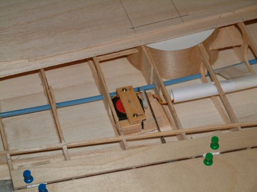
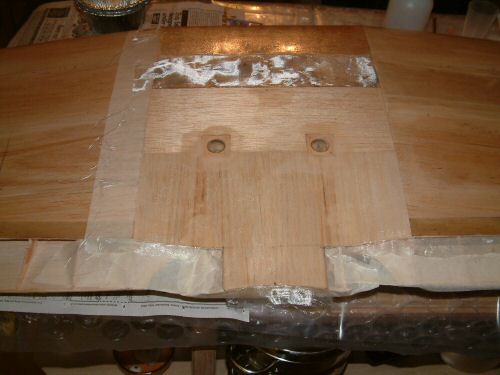
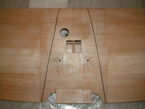
Before I give the wing a primer coat I did 2 more jobs. Pic 1. The outlet for the guns are marked with a small sander on the Dremel. When the model is finally painted red doped cloth will be applied to the leading edge. This notch will give the general impression that there is a hole under the cloth. Pic 2. Fitted to many Spitfires at that time were gun cameras. This orifice housed a small camera that operated for a fixed period of time when the guns or cannon were fired. A carefully prepared hole was cut and a tube of 1/64" ply was applied round a 5 ml syringe. This was fitted to the wing, filled where necessary and sanded to shape. When the model is done I will add a small lens for a little realism. Pic 3. Finally I got the first primer coat on. This highlighted a few blemishes, which are very minor. Generally I am very pleased with the result. I used 180 grit wet & dry to cut it back before applying a second coat as seen in picture. Pic 4. The centre section between the retracts was fabricated from ply and balsa sheet and sanded to fit. The inspection holes for the flap servos were also fabricated similar. |
 |
 |
 |
 |
 |
 |
| 1. Click to enlarge | 2. Click to enlarge | 3. Click to enlarge | 4. Click to enlarge | 5. Click to enlarge | 6. Click to enlarge |
Pic 1. Time to install the wing blisters. None of the supplied blisters from Mick Reeves were suitable for later MKIX's so I had to fabricate them myself. I used reference material and drew up a footprint template on my PC. Pic 2. That done I fabricated the parts from sheet balsa. Shown in the picture are the Hispano cannon blisters cut ready for sanding to shape. Pic 3. Sanding over with I glassed over and gave a quick coat with filler primer. Pic 4. Sanding to the profile of the wing I taped some course sandpaper to the wing over the fitment area and sanded away. To speed the process up I hollowed the blisters first with a Dremel sanding disk. Also shown is the wheel well blister made from a sheet of 1/32" ply and 1/16" balsa sanded to shape with a sponge sander to make the surface nice and round. Pic. 5. After first primer coat I realised the wheel well blister was too deep so I sanded off the balsa sheet and rounded the edges of the 1/32" ply. Picture shows the result after a quick spray with filler primer. Pic 6. The finished article after normal primer coat. |
 |
 |
 |
 |
 |
 |
| 1. Click to enlarge | 2. Click to enlarge | 3. Click to enlarge | 4. Click to enlarge | 5. Click to enlarge | 6. Click to enlarge |
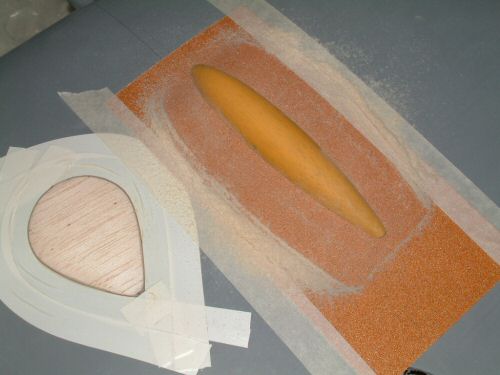
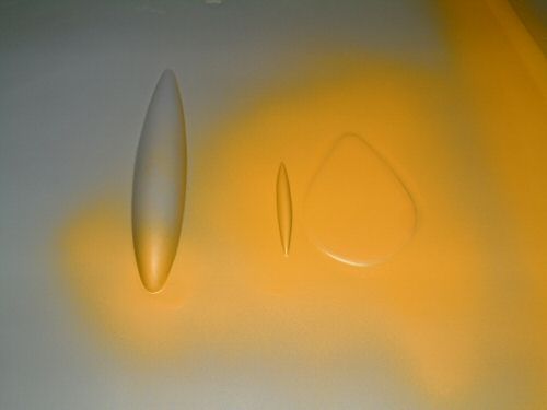
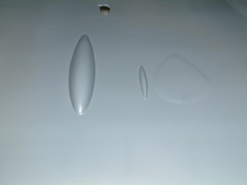
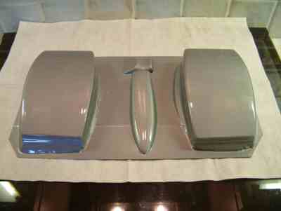
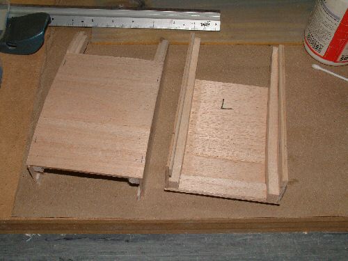
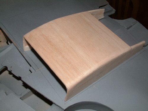
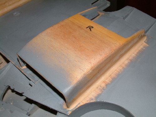
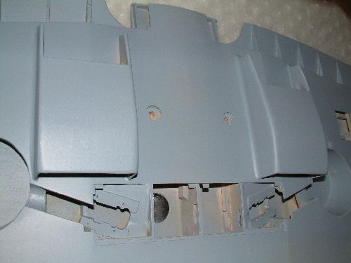
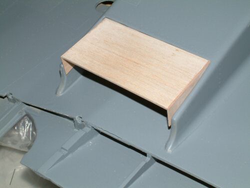
Pic 1. The last big job on the wing is the scoops under the wings. The MKIX has an identical unit under each wing and vacuum formed plastic parts are supplied for this purpose. After some research I discovered that the shape of these parts is not exactly accurate. On the supplied parts both long sides of the rads bulge outward with a nice shapely curve. Typical pictures of MKIX radiators show that they had straight sides with rounded corners (click here for example) I therefore decided to build my own units. Pic 2. Taking dimensions from scale drawings and recreating them in Power Point I put together a basic shell for the rads. Care was needed to take into account the irregular shape of the wing under the radiators to ensure they fitted the contours of the wing. Pic 3. Sanded to shape and ready for glassing the rads begin to look the part already. A separate sheet will be added later to the rear section to reproduce the adjustable exhaust ports which will not be adjustable on this model. Pic 4. Surface prepared and cleaned, they were epoxied into position and the corners filled to form a rounded joint to the wing. Pic 5. After a primer coat they are looking OK. A few wet & dry primer cycles were needed for the final finish. Pic 6. Added much later in the build is the outlets for the scoops. Made from thin balsa laminated with 1/64" ply. They will be installed after painting is completed. The Wing assembly is now complete and work will continue on the finishing page. Click here. |